


2-4
Cisco Unified IP Phone 8961, 9951, and 9971 Administration Guide for Cisco Unified Communications Manager 8.5 (SIP)
OL-20861-01
Chapter 2 Preparing to Install the Cisco Unified IP Phone on Your Network
Providing Power to the Cisco Unified IP Phone
Power Guidelines
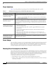
Table 2-1 provides guidelines for powering the Cisco Unified IP Phone 8961, 9951, and 9971.
Power Outage
Your accessibility to emergency service through the phone is dependent on the phone being powered. If
there is an interruption in the power supply, Service and Emergency Calling Service dialing will not
function until power is restored. In the case of a power failure or disruption, you may need to reset or
reconfigure equipment before using the Service or Emergency Calling Service dialing.
Reducing Power Consumption on the Phone
You can reduce the amount of energy that the Cisco Unified IP Phone consumes by scheduling when the
phone goes into power save mode. In power save mode, the backlight on the screen is not lit when the
phone is not in use. The phone remains in power save mode for the scheduled duration or until the user
lifts the handset or presses any button. In the Phone Configuration page on Cisco Unified
Communications Administration, configure the following parameters.
• Days Display Not Active—Specify the days that the backlight remains inactive.
• Display on Time—Schedule the time of day that the backlight automatically activates. on the days
listed in the off schedule.
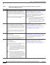
Table 2-1 Guidelines for Powering the Cisco Unified IP Phone 8961, 9951, and 9971
Power Type Guidelines
External power—Provided
through the CP-PWR-CUBE-4=
external power supply.
The Cisco Unified IP Phone 8961, 9951, and 9971 use the CP-PWR-CUBE-4 power
supply.
Note You must use the CP-PWR-CUBE-4 when you deploy the Cisco Unified IP phone
9971 on a wireless Network.
External power—Provided
through the Cisco Unified IP
Phone Power Injector.
The Cisco Unified IP Phone Power Injector may be used with any Cisco Unified IP Phone.
Functioning as a midspan device, the injector delivers inline power to the attached phone.
The Cisco Unified IP Phone Power Injector is connected between a switch port and the IP
Phone, and supports a maximum cable length of 100m between the unpowered switch and
the IP Phone.
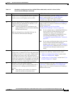
PoE power—Provided by a
switch through the Ethernet
cable attached to the phone.
• Cisco Unified IP Phone 8961, 9951, and 9971 support IEEE 802.3af Class 3 power on
signal pairs and spare pairs.
• Cisco Unified IP Phone 8961, 9951, and 9971 support IEEE 802.3at for external
add-on devices.
• To ensure uninterruptible operation of the phone, make sure that the switch has a
backup power supply.
• Make sure that the CatOS or IOS version running on your switch supports your
intended phone deployment. Refer to the documentation for your switch for operating
system version information.
External power—Provided
through inline power patch
panel WS-PWR-PANEL
The inline power patch panel WS-PWR-PANEL is compatible with the Cisco Unified
IP Phone 8961, 9951, and 9971.