


F-13
Cisco Unified IP Phone 8961, 9951, and 9971 Administration Guide for Cisco Unified Communications Manager 8.5 (SIP)
OL-20861-01
Appendix F Cisco Unified IP Phone Non-Lockable Wall Mount
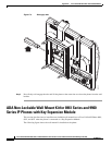
ADA Non-Lockable Wall Mount Kit for 8961 Series and 9900 Series IP Phones with Key Expansion Module
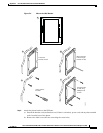
The package contains the following items:
• One phone bracket
• One wall bracket
• Six #8-18 x 1.25-inch Phillips-head screws with six anchors
• Three #4-40 x 0.31-inch machine screws
• One 6-inch Ethernet cable
Before You Begin
You need these tools to install the bracket:
• #1 and #2 Phillips-head screwdrivers
• Level
• Pencil
You must also install an Ethernet jack for the telephone in the desired location if an Ethernet jack does
not currently exist. This jack must be wired appropriately for an Ethernet connection. You cannot use a
regular telephone jack. For more information about phone installation requirements and warnings, see
Setting Up the Cisco Unified IP Phone, page 3-1 and Setting Up the Cisco Unified IP Color Key
Expansion Module, page 4-1.
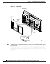
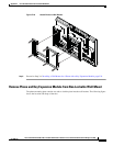
Install Non-Lockable Wall Mount Kit for Phone with Key Expansion Module
The wall mount kit can be mounted on most surfaces, including concrete, brick, and similar hard
surfaces. To mount the kit on concrete, brick, or similar hard surfaces, you must provide the appropriate
screws and anchors for your wall surface.
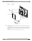
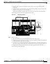
Note Be sure to connect to connect the Cisco Unified IP Phone to the Key Expansion Module before installing
the phone bracket.
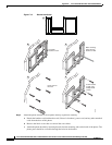
Step 1 Mount the wall bracket in the desired location. You can install the bracket over an Ethernet jack, or you
can run the Ethernet network cable to a nearby jack.
Note If the jack is to be placed behind the phone, the Ethernet jack must be flush to the wall or
recessed.
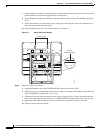
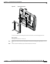
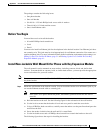
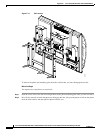
a. Hold the bracket on the wall. See the following figure for the orientation of the wall bracket.
b. Use the level to ensure that the bracket is level and use a pencil to mark the screw holes.
c. Using a #2 Phillips-head screwdriver, carefully center the anchor over the pencil mark and press the
anchor into the wall.
d. Screw the anchor clockwise into the wall until it is seated flush.
e. Use the included screws and a #2 Phillips-head screwdriver to attach the bracket to the wall.
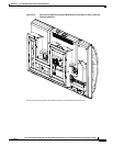
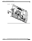
The following figure shows the steps for installing the bracket.