


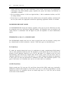

THE DIGITAL LOSS PLAN
4-5
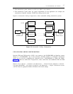
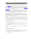
TABLE 4-2. Digital Loss Plan (Port-to-Port Losses)
Transmit
Direction
Receive Direction
(Values in dB Loss)
ONS-
Line
OPS-
Line
ANAL
Tie
COMB
or
Analog
CO Trunk
EIA
DCO
ISL
DTT
ATO
TRK
DTO
TRK
ISL
DCO
TRK
DTT
BAL
N BAL TRK
On-premises station (ONS)
Off-premises station (OPS)
Analog tie trunk (A/TT)
Combination or digital tie trunk (D/TT)
Analog CO trunk (A/CO)
BAL
N BAL
6
3
3
9
0
0
3
3
6
9
3
3
0
2
6
0
0
0
2
3
6
0
3
2
0
3
0
2
2
0
0
3
2
3
0
-3
0
-3
0
0
0
-3
0
-3
0
0
0
3
0
0
0
0
2
6
0
0
0
2
6
0
2
2
2
2
6
2
3
0
2
6
0
2
0
0
3
6
0
3
2
0
6
0
2
0
0
3
6
0
6
3
0
3
2
2
3
3
0
3
3
3
0
-3
0
0
0
0
0
-3
0
0
3
0
2
3
0
2
0
0
3
6
0
EIA digital CO trunk (D/CO 0/6 loss)
ISL digital tie trunk (S/DTT)
analog toll office trunk (A/TO)
digital toll office trunk (D/TO)
ISL digital CO trunk (D/CO -3/3 LOSS)
NOTE: A terminal balanced trunk is defined as meeting an ERL of
≥ 18 dB
and an SRL of
≥ 10 dB, when measured into a quiet termination at the CO.
ANALOG
FACILITY
ANALOG
FACILITY
DS1/DMI
ANALOG
SWITCH
D4
CHANNEL
BANK
DIGITAL
SWITCH
D4
CHANNEL
BANK
ANALOG
SWITCH
ONS
ONS
ONS
ONS
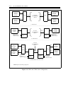
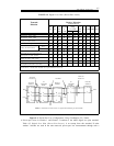
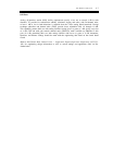
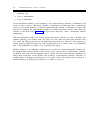
NOTE: A combination tie trunk consists of a digital trunk terminating at a channel bank.
Figure 4-1. End-to-End Loss Configuration Using Combination Tie Trunks
●
Port-to-port losses in Generic 1 and Generic 2 conform to the ANSI digital loss plan standard.
Table 4-2, Digital Loss Plan (Port-to-Port Losses), is an excerpt from this standard. If other
vendors’ switches are used in the same network, port-to-port loss measurements through such a