


NETWORK CONNECTIONS AND CONFIGURATIONS
2-9
Since the D4-channel bank is located at the CO end of a DS1/DMI facility, it is the responsibility of
the CO to set the channel unit attenuators to the appropriate loss values. Chapter 4, The Digital Loss
Plan, includes suggested loss ranges for setting these attenuators.
For synchronization purposes, it should not be assumed that a D4-channel bank (residing in a CO)
will obtain its timing from the AT&T reference frequency. If the D4-channel bank is a standalone
unit at the CO, it should use the DS1/DMI-BOS received from the System 75 or System 85 as its
timing source (loop time). If it is verified that the D4-channel bank is synchronized to the AT&T
reference frequency, then the D4-channel may be used as a synchronization reference.
The DS1/DMI-BOS connections may also be made to any digital CO that does not have DS1 trunks
with a D4-channel bank.
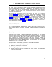
DS1/DMI TERMINAL-EQUIPMENT CONNECTIONS
This section describes the use of DS1/DMI-BOS-compatible external terminal transmission
equipment. The terminal transmission equipment provides additional features and capabilities that
make DS1/DMI-BOS facilities more useful and economical.
DMI-MOS/ISDN-PRI connections to in-series terminal transmission equipment are rarely used. The
options selected for each piece of equipment must be compatible with those selected for the
associated DS1/DMI-BOS.
Since this equipment is external to the switch, an important aspect of its use is how alarms on the
equipment are detected. All external equipment providing alarm outputs should be connected to a
System 75 or 85 external alarm interface. The various alarms and how they are used are also
described.
Since the terminal transmission equipment is in series with a DS1/DMI-BOS facility, the equipment
does not have an effect on the use of the facility as a system clock reference. This is determined by
the final destination of a DS1/DMI-BOS facility.
CDM
Channel division multiplexer (CDMs) are normally paired together in one of two applications. The
first is to emulate a D4-channel bank. The second, more common application uses CDMs to provide
a drop and insert function between switching locations.
When emulating a D4-channel bank, CDMs are used at one or both ends of a DS1 facility. Access to
the individual channels is provided with channel units, same as with channel banks. Most of the
channel units available for the D4 may also be used in the CDM. This allows those DS1/DMI-BOS
channels used by the CDM to be used for the same applications as the D4-channel bank.
Channel units are most frequently used to provide dedicated data connections between a group of
terminals on one end and a computer on the other end. However, voice and some video applications
may also be supported.