


7-108
ADMINISTRATION OPTIONS AND REQUIREMENTS — SYSTEM 75
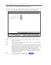
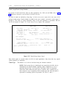
Location A display-only field specifying the carrier and slot of a DS1.
Name The name as shown on the network diagram.
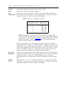
Line Refers to the distance between the switch and the NCTE, CDM, CEM, DSX-1
Compensation cross-connect, T1 office repeater, or other equipment. The compensation setting is
for the total distance between the switch and the endpoint.
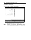
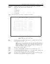
TABLE 7-12. Line Compensation Settings
Compensation Value
Distance (Feet)
1
000 to 133
2
133 to 266
3
266 to 399
4
399 to 533
5
533 to 655
NOTE: Compensation values assume 22-gauge ABAM or 24-gauge PDS
cables. Two colocated switches can be up to 1310 feet apart with compensation
on both systems set to the maximum values. If 26-gauge PDS cables are used,
distances are reduced as shown in table 3-1, System 85 Traditional Module
Equalizer Settings (Metallic Cable).
The T1 office repeaters or T1 line repeaters can be used when the on-premises
distance limitation is exceeded. A T1 office repeater is required at each end of the
connection to provide an interconnection range of up to 3000 feet. Each repeater
only provides regeneration for the receive direction. The T1 line repeaters can be
used to accommodate distances up to 6000 feet between switches. The T1 line
repeaters can be used in tandem to accommodate greater distances.
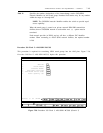
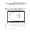
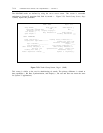
Zero Code
Assigns the line coding format (ZCS or B8ZS) that will be used to forcibly ensure
Suppression that the data meets T1-carrier ones-density requirements. The same considerations
regarding the choice of data rates, communications protocol, and facility
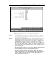
Framing
Mode
requirements that were discussed under System 85 procedure 260, field 9, apply
here.
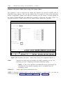
The choices are D4 or ESF (previously referred to as F
e
). The network diagram
should show the choice for the particular DS1/T1-span. The other end and all
intermediate equipment should be optioned accordingly.