


SAMPLE INSTALLATION AND MAINTENANCE PROBLEMS
B-5
the REC or NEC to ensure compatibility between these devices and the associated
communications systems.
CDMs
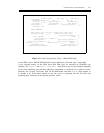
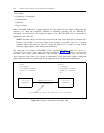
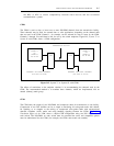
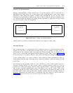
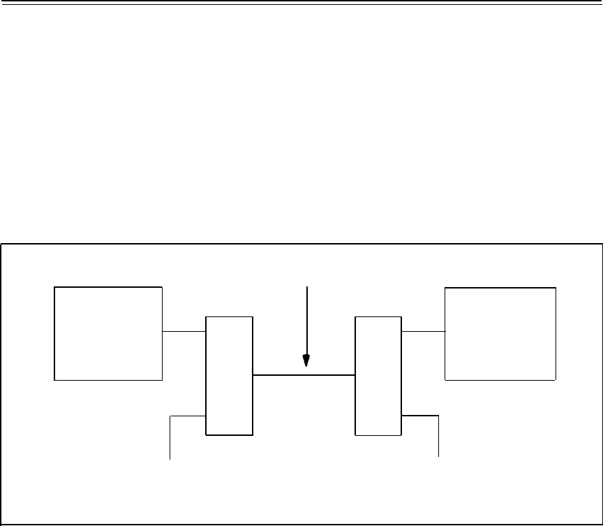
The CDM is used to drop or insert one or more DS1/DMI channels from the transmission facility.
These channels may be used for external data or voice applications, depending on the channel units
that are used in the CDM. Channel 1, for example, can be selected for drop or insert by the CDM.
Channels 2 through 24 would then be left for use by the switch endpoints. Figure B-5, System 75 or
System 85 with CDMs, shows a CDM configuration.
TRANSMISSION FACILITY
SYSTEM 75
OR
SYSTEM 85
DS1 OR DMI
SYSTEM 75
OR
SYSTEM 85
DS1 OR DMI
CDM
CDM
EXTERNAL DEDICATED CHANNELS
(FOR DATA OR VOICE)
EXTERNAL DEDICATED CHANNELS
(FOR DATA OR VOICE)
Figure B-5. System 75 or System 85 with CDMs
The effects of translations to the endpoint switches is in accommodating the channels used by the
CDM. The recommended method is to translate those channels, which are drop/inserted, into an
unused (dummy) trunk group.
CEMs
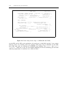
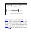
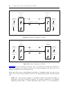
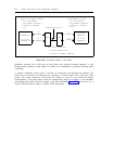
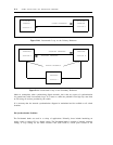
The CEM takes the output of two DS1/DMIs and compresses them for transmission on one facility.
Compression of two DS1 facilities can be as simple as translating 48 voice-grade trunks with robbed-
bit signaling or as complex as the mixing of compressed voice-grade trunks with uncompressed
alternate voice/data (AVD) trunks and using bundling signaling between the CEMs. Figure B-6,
Translation Effects on the CEM, shows a simple CEM configuration using two DS1 facilities from
each switch. The DS1/DMIs on each switch must be translated the same, and compatible options
must be administered for the CEMs (for example, the CEMs must match one another).