


SAMPLE INSTALLATION AND MAINTENANCE PROBLEMS
B-3
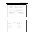
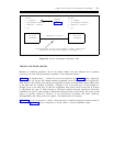
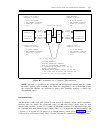
OPTIONS:
OPTIONS:
●
●
●
●
D4 FRAMING
PER-CHANNEL SIGNALING
ROBBED-BIT SIGNALING
ZCS
CHANGED
FROM
FIGURE B-1
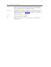
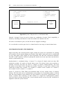
●
●
●
●
D4 FRAMING
PER-CHANNEL SIGNALING
ROBBED-BIT SIGNALING
ZCS
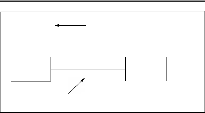
DS1 OR DMI
INTERFACE
TRANSMISSION FACILITY
DS1 OR DMI
INTERFACE
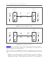
(2-WAY COMMUNICATION)
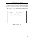
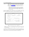
CALL PROCESSING CAN NOW OCCUR ASSUMING CORRECT TRUNK GROUP
TRANSLATIONS AND PROPER ASSIGNMENT IN PROCEDURE 116.
Figure B-2. Correct Translations (Procedure 260)
TRUNKS AND TRUNK GROUPS
Mistakes in translating procedure 116 are not readily evident. The first indication that a problem
exists may not occur until the customer complains of call completion failures.
Table 7-1, DS1 Administration — Channel Versus Line Assignments, and table 7-2, Trunks Supporting
Signaling Type 20, list the DS1 channel number assignments versus slot and circuits for System 85.
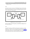
Each end of a DS1 facility must match the assignment of trunks (or off-premises station (OPS) lines)
at the other end. For example, if channels 1 through 12 are to be trunk type 75 and channels 13
through 24 are to be trunk type 36, then the assignments must be the same at each end. If location
A implements the type 75 trunk starting at slot/circuit location 0/0 and location B incorrectly
implements the type 75 trunk starting at slot/circuit location 5/0, then a DS1 facility will come up and
appear to operate. However, because of the translations mismatch and trunk signaling
incompatibilities, the facility will never support a call between the two locations.
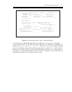
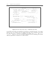
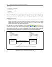
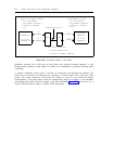
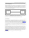
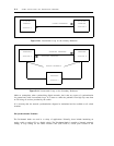
Figure B-3, Incorrect Assignment of Trunks, shows this type of scenario showing an incorrect match of
translations. Figure B-4, Correct Assignment of Trunks, shows a correct translations match.