


ADMINISTRATION OPTIONS AND REQUIREMENTS — SYSTEM 85
7-13
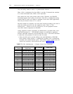
Field 14
V3-V4
Field encodes and their descriptions are:
0
Selects the DS1/DMI-BOS channels used for both trunks and lines; the latter is
frequently referred to as OPS. Each DS1/MFAT carrier will support a maximum
of two DS1s (slots 5 and 18).
The ACCUNET switched digital service can be provided by setting up a trunk
group with encode 109. However, a DS1 must be optioned for RBS (procedure
260, field 8). The only other administration requirement is that the trunk groups
translation (field 3 of procedure 100, word 2) be enabled for 56K-bps encode
one. In a private network, this can be used to pass 56K-bps calls over robbed-bit
facilities.
The trunk group used to provide ACCUNET switched digital service may
contain as few as 1 or as many as 24 members. Therefore, the same DS1 may
also be used to provide CO, foreign exchange (FX), Wide Area
Telecommunications Service (WATS), Direct Inward Dialing (DID), and
Remote Access trunks.
1
Selects the interface is used to provide DMI-BOS trunks. The DMI-BOS trunk
groups are defined by using procedure 100, word 1 (encode 108 and/or 109).
The DMI-BOS application uses the switch’s DS1 to provide a high-speed
multiplexed data interface for connecting to compatible computers. The
computers may be located on the same customer premises as the switch or many
miles away. The DS1/T1-carrier facilities are used between the switch and the
remote computers.
The DMI-BOS application provides 23 data channels plus 1 signaling channel.
Each data channel can be considered a 64K-bps channel. However, permissible
data rates are dependent on the trunk group translations selected in procedure
100, word 2.
24th-channel signaling is the only required service/facility option. All others
(framing format and line-coding format) are DMI application independent.
However, the distant computer and all intermediate T1 transmission equipment
must be compatible.
CAUTION: A loop-timing problem can be created if the synchronization
sources are not administered correctly. The loop-timing problem exists as
the result of an error where both switch endpoints (for the same T1-span)
are administered as the primary. This causes the clock frequency to vary
widely and result in bringing down the switch. Loop-timing problems can be
avoided by following a correctly engineered network synchronization
diagram.
NOTE: Neither DMI-BOS nor DMI-MOS may be used to provide
synchronization to the switch.
2
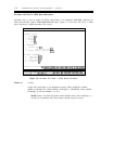
Selects the DS1/DMI-BOS facility that provides 24 lines, called OPS.
DS1/OPS Related Translations
When a DS1 facility is used exclusively for lines, it must be administered for RBS.