


ADMINISTRATION OPTIONS AND REQUIREMENTS — GENERIC 1
7-127
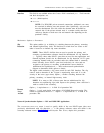
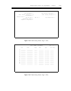
INTERFACE LINKS
Page 1 of 1
Link Enable
Est
Conn
PI
Ext
Destination
Digits
Brd
DTE/
DCE
Prot
Identification
1:
2:
3:
4:
5:
6:
7:
8:
9:
y
n
n
n
n
n
n
n
n
n
n
n
n
n
n
y
_
_
_
_
_
_
_
_
_
_
_
_
_
_
_____
_____
_____
_____
_____
_____
_____
_____
_____
_____
_____
_____
_____
_____
_____
ISDN
_____
_____
_____
_____
_____
_____
_____
_____
_____
_____
_____
_____
____
_____
_____
_____
_____
_____
_____
_____
_____
_____
_____
_____
_____
_____
_____
_____
_____
____
____
____
____
____
____
____
____
____
____
____
____
____
____
____
_ _ _
_ _ _
_ _ _
_ _ _
_ _ _
_ _ _
_ _ _
_ _ _
_ _ _
_ _ _
_ _ _
_ _ _
_ _ _
_ _ _
_ _ _
______________
______________
______________
______________
______________
______________
______________
______________
______________
______________
______________
______________
______________
______________
______________
10:
11:
12:
13:
14:
15:
Link
Enable
Est Conn
PI Ext
Prot
Destination
Digits
Destination
Brd
DTE/DCE
Identification
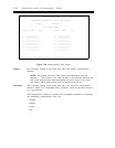
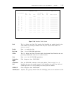
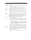
Figure 7-68. Interface Links Screen
This is a display only field. The interface link identified and enabled should be the
same number as previously translated in the Physical Channel field of the
DATA
MODULE
screen.
Enter y to enable the link.
Enter y for all ISDN-PRI applications.
This is a display only field. It should display the phantom Data Extension that was
previously administered with the
DATA MODULE screen.
Enter ISDN for all ISDN-PRI applications,
Field disappears when PROT=ISDN
Enter the ISDN-PRI 4-character circuit pack address. The first digit (1 or 2)
identifies the port, the second character (A-E) identifies the carrier, the third and
fourth digits (01-20 or 01-18) identify the circuit pack slot number.
Field disappears when PROT=ISDN
Optional, but typically should include the identifying name of the destination switch.