


1-16
INTRODUCTION
For System 75, the TN722 provides only AT&T proprietary signaling. However, the TN722B can be
administered to provide either AT&T proprietary signaling or DMI-BOS.
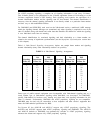
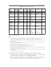
The CCITT Q.921 ISDN-PRI recommendations require that MOS-type signaling be used. In DMI-
MOS, signaling is done with messages that consist of a series of information elements (IEs). The
type of IEs used for a particular signaling message are generally determined by the conditions. (See
the Summary heading later in this chapter for a description of the different types of IEs.)
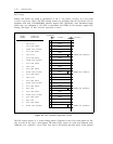
For System 85 R2V4 and Generic 1, each ISDN-PRI facility uses the 24th channel as the D
(signaling) channel. A Generic 2 switch introduced FAS (administered as 23B + 1D), and NFAS
(administered as 24B).
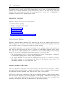
Line-Coding Formats
Line coding is the pattern data assumes as it is propagated over a communications channel.
Governing line coding is a set parameters that must be defined for all digital transmissions. These
transmission parameters specify the voltage level and patterns in which 1s and 0s can appear on the
line.
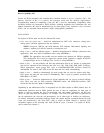
The parameters chosen for a given transmission stream must meet the requirements set by the
hardware through which the data is transmitted. Most notable among these requirements are two
established by the AT&T network. The first of these requirements dictates the voltage levels at
which ones and zeros are transmitted. Alternating mark inversion line coding was adopted to fulfill
this requirement. The second requirement, known as the ones density requirement states that in every
stream of 15 consecutive digits, a one must appear. Zero code suppression (ZCS) and 8-bit zero
substitution (B8ZS) were adopted to meet this requirement. Both ZCS and B8ZS ensure that a one
appears in each consecutive octet in every transmission stream. These line coding formats are
described next in more detail.
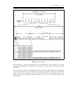
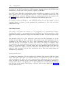
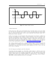
Alternate Mark Inversion
All transmissions generated by DS1s are encoded in the alternating mark inversion (AMI) line coding
format. With AMI, a DS1 signal is a continuous stream of “1s” (encoded as +3V and –3V pulses)
and “0s” (encoded as 0V pulses). For every 1 in the bit stream, a pulse occurs; for every 0, no pulse
occurs. The pulses of successive 1s are of opposite polarity regardless of the number of intervening 0s
(lack of pulses). That is, a the polarity of a 1’s pulse alternates plus or minus between successive
ones. This type of line coding is called bipolar or alternate mark inversion (AMI). (See figure 1-7,
Alternate Mark Inversion.)