


SAMPLE INSTALLATION AND MAINTENANCE PROBLEMS
B-13
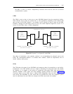
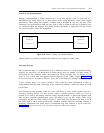
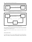
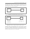
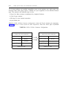
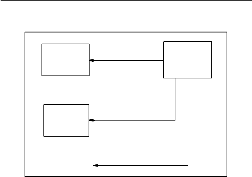
for System 85s that are configured with the ANN11C version 8 or later circuit pack. Figure B-15,
Synchronization from DACS Node, shows a configuration that obtains synchronization from a DACS.
DS1 OR DMI
PRIMARY REFERENCE
DACS
INTERFACE
(STRATUM 3)
LOCATION A
OR BETTER
DS1 OR DMI
INTERFACE
LOCATION B
PRIMARY REFERENCE
PRIMARY REFERENCE
OTHERS
Figure B-15. Synchronization from DACS Node
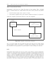
TYPICAL PHYSICAL INTERFACE CONNECTION PROBLEMS
The physical interface from a DS1/DMI circuit pack carrier-cabinet to the transmission facility (such
as the type of cable and cable group numbers) is primarily determined by:
●
Version of the switch and vintage of the circuit pack
●
Type of transmission facility (such as on-premises, off-premises, metallic, or nonmetallic)
●
Any optional transmission products that might be in the circuit
Initially and for the first several System 85s that provided DS1 service, all DS1 connections were
engineered using special shielded cable (type DCC-5/24-TSA cable). This arrangement was
incompatible with the premises distribution system (PDS) and also presented problems for supporting
DMI connections to compatible computers. There were other incompatibilities between various
products in terms of connectors and connector pin assignments.