


MAINTENANCE AND ALARMS
8-3
When procedure 620 is used the following points should be understood:
●
●
●
Procedure 620 consists of five separate tests, identified as tests 1 through 5.
Tests 1, 2, and 3 may be done without affecting service. Tests 4 and 5 affect service.
Test 1 checks all DS1s or DMIs for the presence of any transmission facility faults; if found,
they are stored away until the identified interface has been checked.
NOTE: The alarmed circuit should be checked for hyperactivity before investigating
other possible alarms and before doing demand tests (such as test 2, 3, and so on).
●
●
●
●
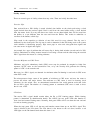
Tests 2, 3, and 4 display facility faults when no other failures are found on the board. TO
localize facility faults it is frequently helpful to use a strategically placed external loop-
around cable.
The second part of test 4 and all of test 5 display all faults found.
Tests 4 and 5 will light the red LED on the circuit pack when facility errors cause procedure
620 to fail. Depending on the type of errors, other LEDs may be in their alarm state.
However, the circuit pack should not necessarily be replaced, because pulling the circuit
pack may cause other facility errors to be introduced.
Excessive circuit pack removals/insertions reduce the life of the carrier.
For ISDN-PRI related errors, there are two unit types. One unit type (75) points toward
ISDN-PRI level-1 faults. The other unit type (76) points toward ISDN-PRI level-2 and level-3
faults.
c. Unit type 75 shows a problem with a particular ISDN-PRI circuit pack. If the identified circuit
pack is currently in service, then the service technician should check the circuit pack’s current
health and status by executing test 1 of procedure 625. If the health code is four or higher, the
service technician should attempt a test call (over the facility) to determine whether the facility
can support service. If the call completes and is of acceptable quality, then additional
maintenance should be deferred until after hours.
However, if the facility is out of service, then procedure 620 should be used to isolate the faulty
hardware.
NOTE: Procedure 620 should not be used to check the status of the circuit pack as it is a
destructive test (service affecting to all 24 channels on the circuit pack) and should only be
used when the facility is unavailable or out-of-hours.
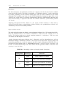
Procedure 620 consists of five separate tests numbered 1 through 5. The following summarizes
the information displayed for these five tests:
●
●
Tests 1, 2, and 3 may be done without affecting service. Tests 4 and 5 affect service.
Test 1 checks all ISDN-PRIs for the presence of any transmission facility faults; if found,
they are stored away until the identified interface has been checked.
NOTE: The alarmed circuit should be checked for hyperactivity before investigating
other possible alarms and before doing demand tests (such as test 2 or 3).
●
●
Tests 2, 3, and 4 display facility faults when no other failures are found on the board. TO
localize facility faults it is frequently helpful to use a strategically placed external loop-
around cable.
The second part of test 4 and all of test 5 display all faults found.