


5-16
SYNCHRONIZATION OF DIGITAL FACILITIES
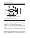
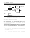
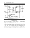
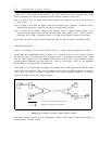
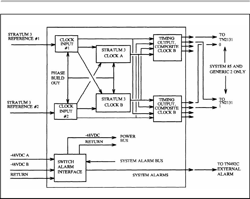
Figure 5-8. External Clock
Private network applications that do not have digital connections to the public network will not
provide the Reference 1 and Reference 2 inputs or the clock-input #1 and clock-input #2 circuit
packs. These types of network applications are not allowed.
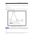
For public-network applications, the clock-input circuit pack derives a 1.544M-bps clock signal from
the reference. The clock #1 and #2 circuit packs generate a 64K-bps stratum-3 clock signal. The
composite clock output circuit pack monitors the 64K-bps signals from the references and clocks and,
on detecting a failure or other error, automatically changes from the online reference clock to an
alternate. Furthermore, an alarm signal alerting you of the problem is generated. Additionally, the
composite clock output circuit pack generates a 64K-bps composite clock signal. This signal is a
special bipolar (return-to-zero) signal that contains a bipolar violation every eighth bit and is cabled
to the switch (for System 85 and Generic 2, the TN2131 circuit pack).