


5-14
SYNCHRONIZATION OF DIGITAL FACILITIES
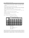
With automatic reference switching enabled, most Generic 1 error counters are decremented by 1
every 15 minutes and initialized to zero on reaching the threshold value. The following conditions
cause an offline reference to be restored to online.
1.
2.
3.
The system configuration maintenance detects DS1 circuit pack sanity (for example, a DS1 has
been reinitialized, reinserted into the carrier, and/or replaced).
The DS1 reference determines that the LOS error no longer exists.
The remote loop-around test is completed.
4.
5.
6.
7.
The red alarm has been cleared.
The blue alarm has been cleared.
The slip error counter has cleared.
The misframe error counter has cleared.
The External Synchronization Clock
Beginning in 1990, all customer premises switches (except for System 75, R1V4, and Generic 1) that
connect to the AT&T public network and transfer timing must use a stratum-4 type-I clock or better
(such a clock already exists in System 75, R1V4). For AT&T customer-premises switches (except
Generic 1), the method chosen to meet this requirement is the external synchronization clock
(Generic 1 uses an internal-clock upgrade). For System 85, the external clock, new cabling, and
TN2131 external clock interface circuit pack are used instead of the SCS-tone clock and its associated
cabling and administration.
One advantage of the stratum-3 clock is that it offers free running accuracy. Using an external
stratum-3 clock, therefore, can avoid many slips when a network is severed.
The external clock may be retrofit into existing System 85s (R2V3 and R2V4). Furthermore, most
Generic 2s will use the external clock. The clock is physically mounted external to the switch
cabinets.
The external clock requires -48VDC power. This power source may be an existing -48VDC power
plant (which is located on customer premises), or one or two cabinet-mounted power supplies. The
input voltage tolerance is -45V to -52V with a worst-case current drain of 3A. Each cabinet mounted
power supply provides up to 10 minutes of holdover.
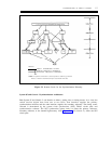
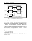
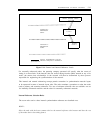
In terms of functional application, the external clock connects between the NCTEs and the switch.
Cabling for the I/O and alarm connections is via 25-pair cables with 50-pin telephone connectors.
The NCTE-to-external clock connection has the same distance limitations as the NCTE-to-DS1
connection (655 feet maximum). For System 85 and Generic 2, the cable run from the external clock
to the TN2131 circuit pack cannot exceed 3000 feet. Cable connections to and from the external
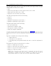
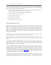
clock will route via the yellow cross-connect field. Figure 5-7, Public-Network External Clock, shows
a public-network configuration of the external clock.
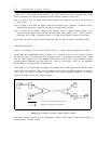
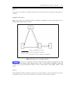
The external clock provides two timing reference inputs and may connect to two NCTEs. These
timing reference inputs are called Reference 1 and Reference 2. They are functionally equivalent to
the primary and secondary references used with the stratum-4 type-I or type-II clock; however, the