


6. PORT TYPES/INSTALLATION COMPATIBILITIES
This chapter describes the operating modes, installation compatibilities, and port types supported by
DS1s. Because of differences between Generic 1 and Generic 2 software and hardware, appropriate
distinctions are identified and separate sections provided.
To date, DS1s have been well accepted. For both Generic 1 and Generic 2, DS1s were initially
available for providing digital tie trunks. Later versions of DS1s and later releases and versions of the
switch software provide additional capabilities. These later version circuit packs are always backward
compatible with previous types.
However, new capabilities that depend on software may only be available on the earlier releases when
the required software is provided, whether the software is a patch or later issue of the tape. Not all
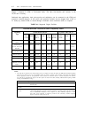
new capabilities are backward compatible to earlier releases and versions. Table 6-1, Supported
Digital Facilities, lists the available capabilities and the hardware and software dependencies.
Engineering problems are minimized by having a good understanding of:
●
●
●
●
●
DS1/DMI, and ISDN-PRI capabilities
Hardware and software compatibility requirements
Services that the particular application requires
All carrier facilities that will be used to complete the end-to-end transmission facility (both local
exchange company (LEC) and toll network carrier)
The labeled network diagram
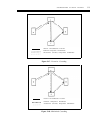
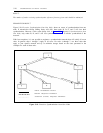
Installation problems are minimized by proceeding from a labeled network diagram. Each DS1 or all
intermediate transmission equipment, such as channel-expansion multiplexers (CEMs), channel-
division multiplexers (CDMs), network channel-terminating equipment (NCTE), network carrier
multiplexers, channel banks, or channel units, should be verified for compatibility. Verification
includes a review of the administration options and, where appropriate, the option-switch settings.
Each end of the channel must be fully compatible For example, if at one end channel 1 is used as a
tie trunk, then channel 1 at the distant end must also be used as a tie trunk. Or, if a group of
channels (for example, 1-16) are administered for call-by-call (CBC) use at one end, then the same
group of channels must also be used for call by call. If, at one switch, extended super framing (ESF),
24th-channel signaling, and the zero code supression (ZCS) line-code format are optioned, then the
distant end and all intermediate facilities must be administered or optioned likewise.
CAUTION: The 551V channel service units will only function with the ZCS line-code format. They
will not pass B8ZS bipolar violations. If the B8ZS line-code format is used for copper carrier
facilities, then the 551V ST (or equivalent) NCTE should be installed and optioned accordingly.
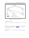
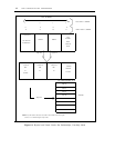
The CDMs are T1 multiplexers that provide an economical means to independently access any of the
24 channels from a DS1 or T1 facility. This access means is called per-channel drop and insert
capability. One line-interface unit, the CDM DS1, connects to the compatible equipment (such as, a
6-1