


7-12
ADMINISTRATION OPTIONS AND REQUIREMENTS — SYSTEM 85
slip count of 44 or less and if the secondary and 50% of those DS1s that are enabled
for slip enable have reached their maximum slip count of 88, then a switch back to
the primary is made.
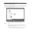
Field 11
V1-V4
Offers the options external loop not available (0) or external loop available (1).
The external loop available option should only be selected when demand diagnostic
maintenance is done and then only after a DS1 has been busied out. If DS1 is a
primary or secondary reference, the reference should be switched off line. This
option is used with procedure 620, test 2, to extend the range of the test to include
the network channel-terminating equipment (NCTE) and the connecting facility.
The external loop available option should only be used for the duration of the test.
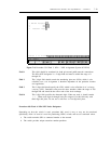
Field 12
V1-V4
Specifies whether (1) or not (0) the associated T1-span is used as an incoming
synchronization source to the switch.
The network synchronization diagram should show those transmission facilities that
are used for synchronization. Each switch permits a maximum of two interfaces
(one primary and one secondary) to be translated (1) in field 12. However, there is
no requirement to have both.
Field 13
V1-V4
Selects whether a DS1 facility (translated in field 12) is to be used as the primary or
secondary synchronization source to the switch. Field encodes and their descriptions
are:
0
1
2
The facility is not used as a synchronization source
The facility is the primary synchronization source
The facility is the secondary synchronization source
NOTE: The primary must be administered before the secondary. The
secondary must be removed before the primary.
Only slots translated (1) and (2) must be configured with synchronization cables.
These cables connect the backplane of the translated ANN11_/ANN35 to the
backplane of the TN463. The cables are identified as group 334 for intercabinet and
group 361 for intracabinet applications.
CAUTION: A loop-timing problem can be created if the synchronization
sources are not administered correctly. The loop-timing problem exists as the
result of an error where both switch endpoints (for the same T1-span) are
administered as the primary. This causes the clock frequency to vary widely and
result in bringing down the switch. Loop-timing problems can be avoided by
following a correctly engineered network synchronization diagram.