


ADMINISTRATION OPTIONS AND REQUIREMENTS — GENERIC 2
7-53
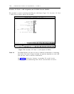
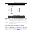
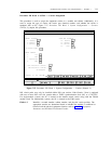
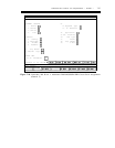
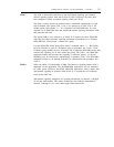
Procedure 250 Word 1: SC/DS1 — Carrier Designation
This procedure is used to assign the equipment carriers to a module and cabinet. Additionally, it is
used to assign the type of carrier, the carrier port electrical number, and whether the carrier is
equipped with an SC. Figure 7-27, Procedure 250 Word 1: System Configuration — Carriers
(Generic 2), depicts this procedure.
ENHANCED MODE - PROCEDURE: 250, WORD: 1
CARRIERS
CARRIER LOCATION LOCAL RMI LOCATION
1.
2.
3.
Module:
Cabinet:
Carrier:
12.
13.
14.
15.
Module:
Cabinet:
Carrier:
Slot:
4. Carrier Type:
MODULE CONTROL
5.
6.
7.
8.
I/O:
PDS:
Duplicated:
TMS:
9.
10.
11.
Port Electrical Carrier:
TMS Electrical Carrier:
SC Equipped:
Connected to CC0 ON-LINE
enter command:
Figure 7-27. Procedure 250 Word 1: System Configuration — Carriers (Generic 2)
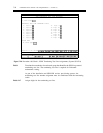
DS1 circuit packs may only be installed within DS1 port carriers. Each Generic 2 that is equipped
with one or more DS1s will also contain either a TN463 synchronization clock (SC) or a TN2131C.
For single-module systems, the SC is located in the module control carrier along with the TN460
module clock. For multimodule systems, the SC is located in the TMS carrier.
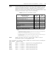
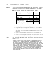
Fields 1-3 Identifies a module number, cabinet number, and physical carrier position. The
appropriate encodes are determined based on whether the module is traditional or
universal and the physical equipment location, refer to table 7-6, Equipment
Parameters and Permitted Translation Encodes.