


7-92
ADMINISTRATION OPTIONS AND REQUIREMENTS — GENERIC 2
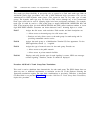
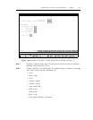
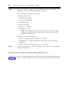
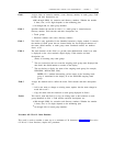
Procedure 116 Word 1: DS1/DMI/ISDN-PRI Trunk Assignments
For more information, see the chapter in this book entitled Port Types and Installation
Compatibilities. Each analog trunk circuit pack provides four circuits that are administered by using
procedure 150. Conversely, each DS1 provides 24 circuits (channels) that are administered by using
procedure 116.
For traditional modules, each DS1/MFAT carrier will support a maximum of two DS1s, each
occupying one slot and located in slots 5 and 18. When a DS1/DMI/ISDN interface (trunk
applications) is located in slot 5, it functionally uses the six slots 0, 1, 2, 5, 6, and 7. When the
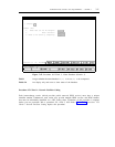
interface is located in slot 18, it functionally uses the six slots 13, 14, 15, 18, 19, and 20. Figure 7-
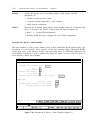
44, Procedure 116 Word 1: DS1/DMI/ISDN-PRI Trunk Assignments, depicts this procedure.
ENHANCED MODE - PROCEDURE: 116, WORD: 1
DS1 AND ISDN TRUNK ASSIGNMENTS
EQUIPMENT LOCATION
1.
2.
3.
4.
5.
Module:
Cabinet:
Carrier:
Slot:
Circuit:
6.
7.
8.
9.
Trunk Group:
Night Terminal:
Disable Signaling:
AIOD Equipment Number:
10.
11.
Interface Endpoint:
D-Channel Group Number:
Connected to CC0 ON-LINE
enter command:
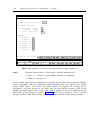
Figure 7-44. Procedure 116 Word 1: DS1/DMI/ISDN-PRI Trunk Assignments (Generic 2)
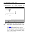
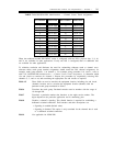
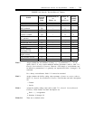
The DS1 channels are assigned to slot and circuit locations according to the order in which the
module processor scans the equipment carrier as shown in table 7-10, DS1/ISDN-PRI Administration
— Channel Versus Trunk Assignments.
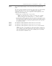
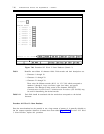
When the traditional module DS1/MFAT carrier is configured with two DS1s, physical slots 3, 8, 16,
and 21 are available for other applications. If only one DS1 is configured, then six additional slots
are available for other applications.