


7-64
ADMINISTRATION OPTIONS AND REQUIREMENTS — GENERIC 2
Field 18
Loop length refers to the total cable distance between the switch and the NCTE,
CDM, BCM32000, DSX-1 cross-connect, and T1 office repeater. Traditional
modules may contain the ANN11 and/or ANN35 circuit packs. Both circuit packs
contain DIP switches for setting the compensation value, refer to table 3-1, System
85 Traditional Module Equalizer Settings (Metallic Cable). Therefore, software
administration is not applicable and the (–) should be administered for traditional
modules.
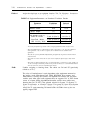
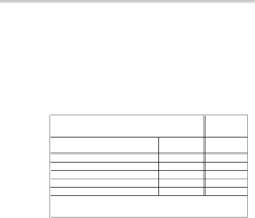
Universal modules may contain the TN767 circuit pack. Line compensation value
be administered in software. Table 7-7, TN767 Compensation Values, identifies the
appropriate administration encode for distance intervals of 133 feet up to a
maximum distance of 655 feet.
TABLE 7-7. TN767 Compensation Values
Distance to Midpoint
Compensation
or Endpoint (FT)
22 AWG ABAM & 24 AWG PDS
26 AWG PDS
Value
0 to 133 0 to 90
0
133 to 266
90 to 180
1
266 to 399
180 to 270
2
399 to 532
270 to 360
3
532 to 665
360 to 450
4
NOTE: Compensation values assume 22-gauge ABAM or 24-gauge PDS cables. Two switches
(colocated) can be up to 1310 feet apart with maximum compensation on both systems. If 26-gauge
PDS cables are used, distances are reduced as assigned.
The T1 office repeaters or T1 line repeaters can be used when the on-premises
distance limitation is exceeded. A T1 office repeater is required at each end of the
connection to provide an interconnection range of up to 3000 feet. Each repeater
only provides regeneration for the receive direction. The T1 line repeaters can be
used to accommodate distances up to 6000 feet between switches. The T1 line
repeaters can be used in tandem to accommodate greater distances.
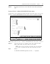
Field 19
Field encodes and their descriptions are:
–
0
1
(Dash) required option for all traditional modules. It is also required for all
ISDN-PRI links provided with universal modules.
Preferred for DS1 service provided with universal modules (shows that a DS1
provides standard DMI-BOS).
Assigns that the DS1 provides the AT&T proprietary method of signaling on the
24th channel. This option is required when connection to System 75 that still has
the TN722 circuit packs.
NOTE: When connecting to a TN722B or ANN11 circuit pack, the
recommended option is
(0).