


ADMINISTRATION OPTIONS AND REQUIREMENTS — SYSTEM 75
7-107
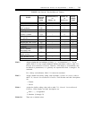
SYSTEM 75 (R1V2 AND R1V3)
System 75 has the same facility considerations (framing, signaling, line coding format, etc.) as System
85 or Generic 2 and many similar equipment considerations (both require an additional clock circuit
pack for synchronization). The main differences are in terms of administration methods (screens for
System 75 versus procedures for System 85), and for some fields a difference in terminology. The
primary equipment differences are:
●
No synchronization cables are required.
●
Line compensation is translated in software rather than set by DIP switches.
All screens shown have their fields depicting default or recommended options.
Service/Facility Options
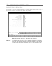
The
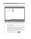
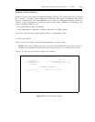
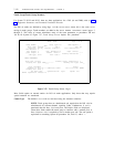
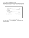
DS1 CIRCUIT PACK screen is used to define characteristics of a DS1 facility.
NOTE: This screen requires that the circuit pack (TN722/TN722B) have been previously
assigned to an equipment location (carrier and slot) by the
CIRCUIT PACK ADMINISTRATION screen.
Figure 7-55, DS1 Circuit Pack Screen, depicts this procedure.
DS1 CIRCUIT PACK Page 1 of 1
Location:
Line Compensation:
Framing Mode:
DMI-BOS?
___
1
esf
y
Name:
Zero Code Suppression:
____________
zcs
Signaling Mode: common-chan
MAINTENANCE PARAMETERS
Slip Detection? n
Remote Loop-Around Test? n
Figure 7-55. DS1 Circuit Pack Screen