


ADMINISTRATION OPTIONS AND REQUIREMENTS — SYSTEM 85
7-37
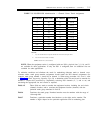
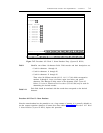
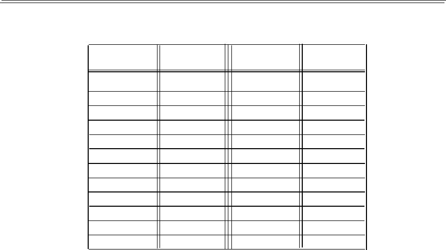
TABLE 7-3. DS1/ISDN-PRI Administration — Channel Versus Trunk Assignments
DS1 Channel Slot/Circuit
DS1 Channel
Slot/Circuit
1
*/0
13
*+1/0
2
*/1 14
*+1/1
3
*/2
15
*+1/2
*/3
4
16
*+1/3
5
*/4
17
*+1/4
6
*/5
18
* +1/5
7
*/6
19
*+1/6
8
*/7
20
*+1/7
*/8
9
21
*+1/8
10
*/9
22
*+1/9
11
*/1O
23
*+1/10
12
*/11
24
*+1/11
LEGEND:
*
Any slot for the TN767 except slot number one in the universal port carrier.
*+
1
The slot next to the TN767 or TN555.
NOTE: Channel 24 is the D-channel.
NOTE: When the equipment carrier is configured with two DS1s, physical slots 3, 8, 16, and 21
are available for other applications. If only one DS1 is configured, then six additional slots are
available for other applications.
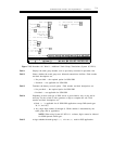
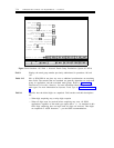
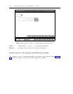
To minimize confusion and eliminate the need for maintaining elaborate trunk to channel cross-
reference tables, trunk group member assignments should match the DS1 channel assignments (for
example, trunk group member 1 should be on channel 1). When using procedure 116, word 1, refer
to Table 7-2, Trunks Supporting Signaling Type 20, to determine which slot and circuit to translate for
channel 1. Repeat this procedure by sequentially selecting DS1 channels (2, 3, and so on) and
translating the appropriate slot and circuits as required.
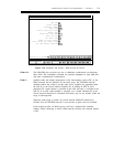
Fields 1-5
These fields are used to translate the equipment location, including slot and circuit
(channel) location, and to associate the equipment location (channel) with the
particular trunk group translated in field 6.
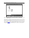
Field 6 Translates the trunk group. Permitted encodes must be numbers with the range of
18 through 999.
Field 7
Translates a particular number that functions as the night service number. The
number of digits depend on the particular application and its numbering plan.