xvi
CONTENTS
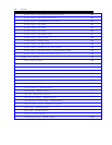
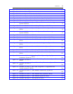
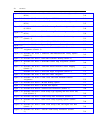
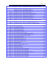
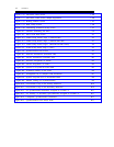
Figure 7-76.
Figure 7-77.
Figure 7-78.
Figure 7-79.
Figure 7-80.
Figure 8-1.
Figure A-1.
Figure A-2.
Figure A-3.
Figure A-4.
Figure A-5.
Figure A-6.
Figure B-1.
Figure B-2.
Figure B-3.
Figure B-4.
Figure B-5.
Figure B-6.
Figure B-7.
Figure B-8.
Figure B-9.
Figure B-10.
Figure B-11.
Figure B-12.
Figure B-13.
Figure B-14.
Figure B-15.
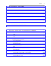
SID Prefix Table Screen
SID Prefix Table Screen, Sample Application
Routing Patterns Screen
Hunt Group Screen
Terminating Extension Group Screen
Facilities Generating the RFA
DS1 Circuit Pack Screen
Trunk Group Screen, Page 1 (MEGACOM)
Trunk Group Screen, Page 1 (MEGACOM 800)
Trunk Group Screen, Page 1 (MEGACOM 800 DNIS)
Trunk Group Screen, Page 1 (SDN)
Synchronization Plan Screen
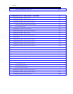
Incorrect Translations (Procedure 260)
Correct Translations (Procedure 260)
Incorrect Assignment of Trunks
Correct Assignment of Trunks
System 75 or System 85 with CDMs
Translation Effects on the CEM
Arrangement for a Complex CEM Installation
System 75/System 85 to a D4-Channel Bank
Internal Timing (No Synchronization)
Leavenworth Loop on the Primary Reference
Leavenworth Loop on the Secondary Reference
No Synchronization Reference Assigned at Location A
No, Primary, or Secondary Sync Reference Assigned at Location A
Compatible Synchronization References
Synchronization from DACS Node
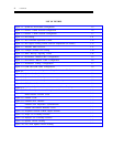
7-144
7-146
7-147
7-150
7-151
8-9
A-1
A-2
A-3
A-4
A-5
A-5
B-2
B-3
B-4
B-4
B-5
B-6
B-7
B-8
B-9
B-10
B-10
B-11
B-11
B-12
B-13


