


SAMPLE INSTALLATION AND MAINTENANCE PROBLEMS
B-7
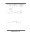
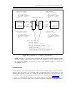
SYSTEM 75 OR SYSTEM 85
INTERFACE A OPTIONS:
●
D4 OR ESF FRAMING
●
PER-CHANNEL SIGNALING
●
ROBBED-BIT SIGNALING
●
ZCS
OTHER ENDPOINT
INTERFACE A OPTIONS:
●
D4 OR ESF FRAMING
●
PER-CHANNEL SIGNALING
●
ROBBED-BIT SIGNALING
●
ZCS
TRANSMISSION FACILITY
DS1 OR DMI
INTERFACE A
12 AVD
TRUNKS
12 AVD
TRUNKS
DS1 OR DMI
INTERFACE A
CEM
CEM
DS1 OR DMI
INTERFACE B
21 VOICE-
GRADE
TRUNKS
21 VOICE-
GRADE
TRUNKS
DS1 OR DMI
INTERFACE B
SYSTEM 75 OR SYSTEM 85
INTERFACE B OPTIONS:
●
D4 OR ESF FRAMING
●
PER-CHANNEL SIGNALING
●
ROBBED-BIT SIGNALING
●
ZCS
OTHER ENDPOINT
INTERFACE B OPTIONS:
●
D4 OR ESF FRAMING
●
PER-CHANNEL SIGNALING
●
ROBBED-BIT SIGNALING
●
ZCS
CEM OPTIONS:(BOTH ENDS)
●
BUNDLING SIGNALING
●
SELECTED COMPRESSED CHANNELS
●
SELECTED UNCOMPRESSED CHANNELS
●
NO SIGNALING ON AVD TRUNKS SINCE THEY ARE
ON THE 24TH CHANNEL
●
THE SECOND DELTA CHANNEL (CHANNEL 24) FOR THE
12 AVD TRUNKS MUST BE SHIFTED PER STANDARD CEM
OPTIONS TO CARRY THE 24TH CHANNEL INTACT
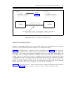
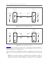
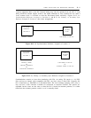
Figure B-7. Arrangement for a Complex CEM Installation
NOTE: Although it is possible to mix compressed and uncompressed channels with the variable
bit-robbed signaling option installed in the CEM, this arrangement is not recommended because
the compressed channels are restricted to analog data. Bundling signaling is always the
recommended option.
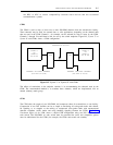
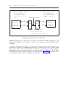
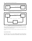
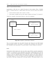
D4-Channel Banks
The D4-channel banks used with System 75 and System 85 networks require simple translations.
However, there are pitfalls. The D4-channel banks use individual plug-in circuit packs for each
channel (trunk interface). System 75 or System 85 DS1/DMI connected to a D4-channel bank must
be compatible with those installed plug-in channel units. It is recommended that unused channels (in
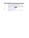
a System 75 or System 85) be placed in an unused (dummy) trunk group. Figure B-8, System
75/System 85 to a D4-Channel Bank, shows a System 75/System 85 connection to a D4-channel bank.