


SYNCHRONIZATION OF DIGITAL FACILITIES
5-17
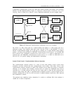
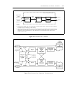
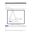
TN2131 CIRCUIT PACK
COMPOSITE
CLOCK
OUTPUT #1
COMPOSITE
CLOCK
CONVERTER
SYNC
CABLES
ALARMS
NOTE 1
LOS
DETECTION
COMPOSITE
CLOCK
OUTPUT #2
SYNC
OUTPUT
NOTE 2
NOTES:
1.
2.
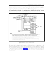
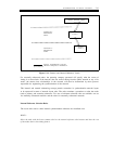
Alarm signals are cabled to the cross-connect field. For System 85 and Generic 2, they are then cross-connected
and cabled back to the maintenance or CPE interface.
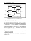
System 85 and Generic 2 applications require that the composite clock synchronization signal be connected to the
module control or TMS carrier via an intercarrier cable. Traditional module control carriers (for both System 85
and Generic 2) use the H-600-260 group 1 cable, while Generic 2 universal module control carriers use the
H-600-271 group 1 cable.
Figure 5-9. External-Clock Interface
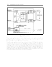
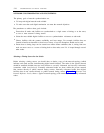
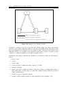
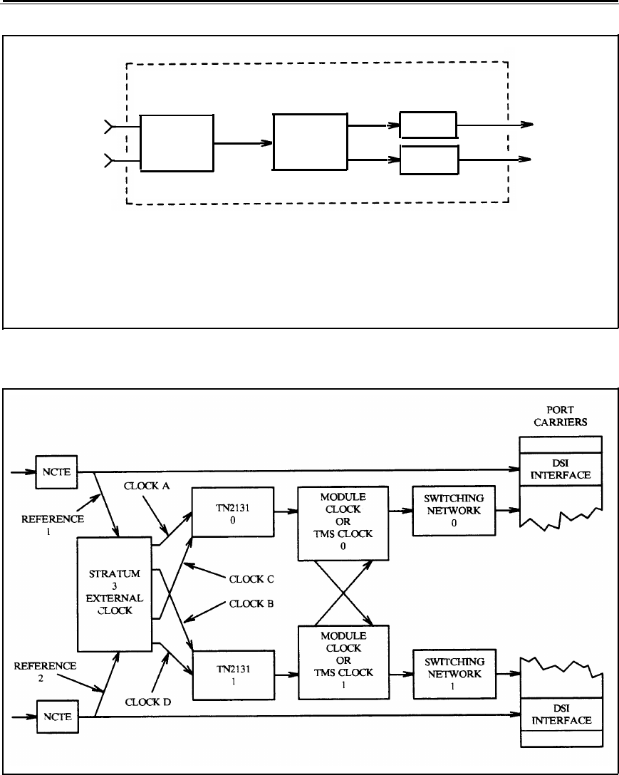
Figure 5-10. External-Clock Duplicated Synchronization