


SAMPLE INSTALLATION AND MAINTENANCE PROBLEMS
B-17
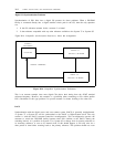
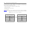
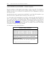
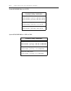
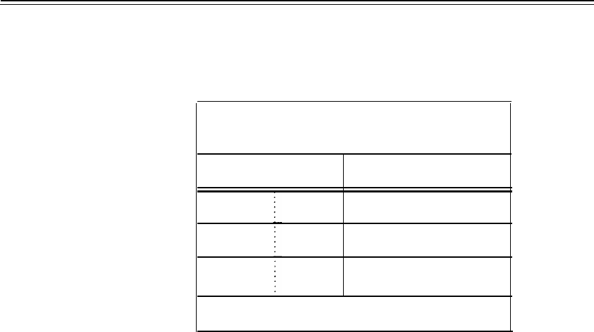
TABLE B-4. 8-Position Modular Jack Pin Assignments (System 75 and System 85 Perspective)
DS1 OR DMI PINOUT FOR
8-PIN MODULAR JACK (NOTE 1)
PIN NUMBERS
FUNCTION
1
3
4
2
6
5
RECEIVE
LOOPBACK (NOTE 2)
TRANSMIT
OTHERS NOT USED
NOTES:
1.
The modular jack may be either the RJ48C or the RJ48X connector.
2.
Signal leads 3 and 6 are unused or used for loop feedback.
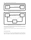
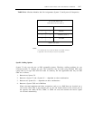
Specific Cabling Options
System 75 only uses the new or PDS compatible pinouts. Therefore, cabling problems for two
colocated System 75 switches are rare. The connection may be made using standard PDS cable
(group 300) or via type DCC-5/24-TSA cable. In summary, the four applications that may use PDS
cable are as follows:
1.
2.
3.
4.
Between two System 75s
Between a System 75 and a System 85 — dependent on other considerations
Between two System 85s — dependent on other considerations
Between a System 75/85 and a DMI host
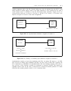
Where colocated equipment and direct connections (such as to a DMI host) are involved, use a
null modem cable. That is, the transmit pair on one end should connect to the receive pair on
the opposite end. When NCTEs, CDMs, or CEMs are used, the transmit and receive signals
are reversed automatically.