


SYNCHRONIZATION OF DIGITAL FACILITIES
5-11
monitored to make sure that a switch is not attempted to an unhealthy SCS. If the SCS is not
duplicated and the HAC is healthy, serious failures cause a switch to the HAC to ensure switch
reliability. When the SCS can once more lock onto a DS1 reference, a switch to that reference is
performed.
Synchronization occurs at several priority levels; records are kept for perusal at the demand test level
with procedure 625. In addition, several yellow LEDs on the SCS can be observed to get a current
picture of how the system is configured from a reference clock point of view.
●
●
●
The LED in position #4 refers to the primary DS1 reference. The LED is OFF if a
synchronization signal is present and the SCS is capable of locking. The #4 LED is ON if an
error condition exists and the synchronization cable is present.
The LED in position #5 refers to the secondary DS1 reference. The LED is OFF if a
synchronization signal is present and the SCS is capable of locking. The #5 LED is ON if an
error condition exists and the synchronization cable is present.
The following four yellow LEDs indicate the selected timing reference: #14 (HAC), #15
(primary reference), #16 (secondary reference), and #17 (cross-coupling). When the system is
first brought up and no references are administered, the HAC LED should be lit for the online
SCS and the cross-coupling LED should be lit for the offline SCS. Shortly after the DS1
references are administered, the primary reference LED should turn on and the HAC LED should
turn off for the online SCS. The cross-coupling LED is the only one lit for the offline SCS.
The synchronization subsystem described above also functions as a periodic maintenance monitor.
Status detected during the synchronization process is passed along to other levels of maintenance
software for processing. This processing includes error logging for procedure 600 and alarming.
CHANGES TO THE SCS SOFTWARE MADE AVAILABLE VIA SOFTWARE PATCHES
The following changes (regarding the SCS software) may apply, providing that the appropriate
patches have been installed.
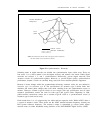
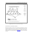
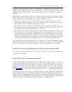
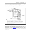
System 75 and Generic 1 Synchronization Architecture
System 75 and Generic 1 can function as either a timing slave or timing master. As a slave, the
switch receives digital data from one or two DS1s. One interface supplies the primary
synchronization reference; the other supplies the secondary reference. The timing source selected is
determined by the tone-clock circuit pack and maintenance software. The tone clock synchronizes
(phase locks) to either the primary reference, secondary reference, or the internal high-accuracy
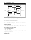
clock. Figure 5-6, Tone-Clock Synchronizer (Nonduplicated, Generic 1), shows the tone clock circuit.
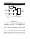
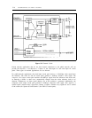
The DS1 that is used as the primary or secondary reference is totally dependent on administration
details. Although there are no restrictions on placing one or both synchronization references in the
second cabinet, it is recommended that the references be located in the first cabinet (processor port
network) to maximize reliability. The tone clock generates the call-processing system tones and also
provides the switch with the stratum-4 clock in the absence of a reliable reference.