


SYNCHRONIZATION OF DIGITAL FACILITIES
5-23
Facility rank ordering is generally based on limited technical and operational information. It is
recommended that facility selections be based on local field experience where available.
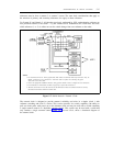
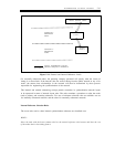
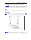
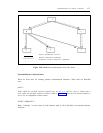
In figure 5-14, Improper Use of Backup Facilities, only node C has both a primary and a secondary
frequency reference. Node C derives its primary source from node B and its secondary timing source
from node D. This configuration is optimal because if either node B, D, or the interconnecting
facilities should fail, node C would still receive timing traceable to node A from the other node.
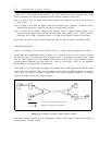
RULE 4:
Where possible, the routes for all primary and secondary synchronization facilities should be diverse.
EXAMPLE FOR RULE 4
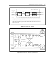
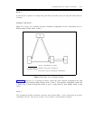
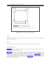
Figure 5-15, Optimal Diverse Routing, explains the optimal configuration when rule 4 is used. Figure
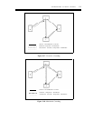
5-16, Less Than Optimal Diverse Routing, shows a less than optimal application of rule 4.
DIGITAL TRANSMISSION FACILITY
PRIMARY FREQUENCY REFERENCE
SECONDARY (BACKUP) FREQUENCY REFERENCE
Figure 5-15. Optimal Diverse Routing
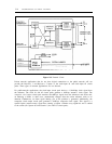
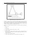
Figure 5-16, Less Than Optimal Diverse Routing, shows node C deriving both primary and secondary
timing from node D, via the two separate T1 facilities. If node D should fail, node C would no
longer receive timing that is traceable to node A. Here, node C would lose synchronization and
begin to introduce slips into the network.