


DS1 TRANSMISSION AND CABLING
3-7
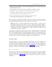
The transmission system connects to a DS1 via a DSX-1 cross-connect●
●
The transmission system meets any special requirements for the application (for example, the
transmission of bipolar violations if B8ZS line coding must be used)
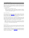
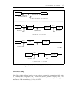
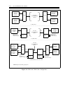
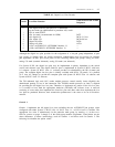
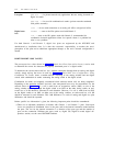
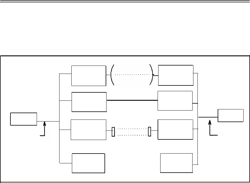
Figure 3-3, Nonmetallic Cabling Configurations, shows nonmetallic cabling transmission systems.
MICROWAVE
INTERFACE
MICROWAVE
INTERFACE
DS1/DMI
LIGHT-GUIDE
'INTERFACE
LIGHT-GUIDE
INTERFACE
DSX-1
DSX-1
DS1
DS1
INFRARED
INTERFACE
INFRARED
INTERFACE
655 FT
MAXIMUM
655 FT
MAXIMUM
ANY DSX-1
INTERFACE
––––––––––––––
ANY DSX-1
INTERFACE
Figure 3-3. Nonmetallic Cabling Configurations
CEM AND CDM CABLING CONFIGURATIONS
Both the CEM and CDM provide a DSX-1 cross-connect to the DS1/DMI-BOS and therefore connect
directly to a DS1/DMI-BOS. Any of the previously described metallic or nonmetallic transmission
media may be used for completing the connection from a DS1/DMI-BOS to CEMs and CDMs.
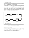
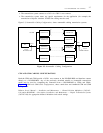
Figure 3-4, CEM and CDM Cable Configurations, shows stand alone and combined CEM and CDM
configurations.
Refer to Service Manual — Installation and Maintenance — Channel Division Multiplexer (365-165-
101) and to BCM32000 — Description, Installation, and Maintenance — Digital Transmission Systems
(365-287-100) for appropriate distance limitations and switch settings.