


1-12
INTRODUCTION
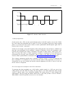
ESF Framing
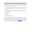
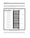
Initially, this format was called F , pronounced “F sub e,” for framing extended. It is now called
e
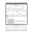
extended superframe (ESF). The ESF framing format was developed after the D4 format. Not all
equipment used with a DS1/DMI-BOS interface supports ESF. Specifically, most D4-channel banks
(unless they are configured as LIU-3ESF or equivalent) and CDMs do not currently support ESF
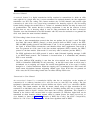
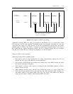
framing. (See figure 1-5, DS1 Extended Superframe Format.)
FRAME BIT
FRAME
NUMBER
FRAME BIT
DEFINITIONS
CHANNEL 1
CHANNEL 2
1
2
3
4
5
6
7
8
9
DATA LINK F BIT (DL)
CRC-6 F BIT
DATA LINK SIGNAL
FRAME SYNC PATTERN
DATA LINK SIGNAL
CRC-6 F BIT
DATA LINK SIGNAL
FRAME SYNC PATTERN
DATA LINK SIGNAL
0
0
1B
8-BITS
8-BITS
8-BITS
8-BITS
8-BITS
7-BITS
8-BITS
8-BITS
8-BITS
8-BITS
8-BITS
7-BITS
8-BITS
8-BITS
8-BITS
8-BITS
8-BITS
7-BITS
8-BITS
8-BITS
8-BITS
8-BITS
8-BITS
7-BITS
A ROBBED BIT (OPTIONAL)
10
11
12
13
14
15
16
17
18
CRC-6 F BIT
DATA LINK SIGNAL
FRAME SYNC PATTERN
DATA LINK SIGNAL
CRC-6 F BIT
DATA LINK SIGNAL
FRAME SYNC PATTERN
DATA LINK SIGNAL
ROBBED BIT (OPTIONAL)
0
C
ROBBED BIT (OPTIONAL)
19
20
21
22
23
24
CRC-6 F BIT
DATA LINK SIGNAL
FRAME SYNC PATTERN
DATA LINK SIGNAL
CRC-6 F BIT
DATA LINK SIGNAL
FRAME SYNC PATTERN
1
1D
ROBBED BIT (OPTIONAL)
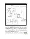
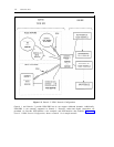
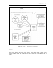
Figure 1-5. DS1 Extended Superframe Format
The ESF format consists of a 24-bit framing pattern. Compared to the 12-bit fixed pattern for D4,
only 6 of the 24 bits carry a fixed pattern. The other 18-bits consist of a 6-bit error detection code,
called the cyclic redundancy check (CRC) sum, and a 12-bit facility data link signal. At the transmit