


7-146
ADMINISTRATION OPTIONS AND REQUIREMENTS — GENERIC 1
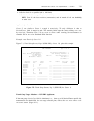
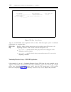
SID PREFIX TABLE
Page 1 of 5
Ext
Len
Ext
Code
SID
Prefix
Ext
Len
Ext
Code
SID
Prefix
Ext
Len
Ext
Code
SID
Prefix
5
5
_
_
_
_
_
_
_
_
_
_
_
_
_
_
31
41
_____
_____
_____
_____
_____
_____
_____
_____
_____
_____
_____
_____
_____
_____
2012353000
20123
__________
__________
__________
__________
__________
__________
__________
__________
__________
__________
__________
__________
__________
__________
_
_
_
_
_
_
_
_
_
_
_
_
_
_
_
_
____
____
____
____
____
____
____
____
____
____
____
____
____
____
____
____
__________
__________
__________
__________
__________
__________
__________
__________
__________
__________
__________
__________
__________
__________
__________
__________
_
_
_
_
_
_
_
_
_
_
_
_
_
_
_
_
____
____
____
____
____
____
____
____
____
____
____
____
____
____
____
____
__________
__________
__________
__________
__________
__________
__________
__________
__________
__________
__________
__________
__________
__________
__________
__________
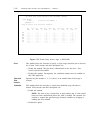
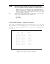
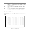
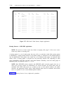
Figure 7-77. SID Prefix Table Screen, Sample Application
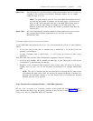
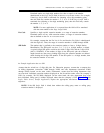
Routing Patterns — ISDN-PRI Applications
NOTE: The
ROUTING PATTERN screen only relates to outgoing calls; page 2 of the TRUNK GROUP
screen only relates to incoming calls.
A routing pattern is a set of trunk groups that carry calls to a particular switch. Each routing pattern
is identified by a unique number known as the pattern number. A maximum of 254 different patterns
may be administered. Each pattern may contain up to six different trunk groups (six alternate trunk
routes). Once a routing pattern is accessed the call processing software will, depending on trunk
group compatibility (both FRL and BCC) and trunk member availability, select the trunk groups in
decreasing order of preference (that is, 1, 2,...6).
NOTE: Both ISDN-PRI private networks and ISDN-PRI public networks require that one or
more
ROUTE-PATTERN screens be administered. For private networks, the RNX tables must be
translated. Each RNX table serves as a pointer to one or more pattern numbers. For public
networks, the appropriate HNPA, FNPA, and/or RHNPA tables must be translated. These tables
serve as a pointer to one or more different pattern numbers.
Figure 7-78, Routing Patterns Screen, depicts this procedure.