


1-20 INTRODUCTION
Bipolar Violations
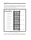
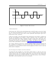
As noted earlier, the DS1 bit stream is transmitted as a series of pulses. Successive pulses, regardless
of the number of intervening spaces (0s), are of opposite polarity. A bipolar violation is the
occurrence of two consecutive identical pulses, that is, when two positive or two negative pulses are
received in a row, regardless of the number of intervening 0s.
Usually, bipolar violations are caused by noise hits on the DS1 bit stream. For B8ZS, strings of eight
0s are encoded into special sequences that include bipolar violations. Some network-interface
equipment, primarily most network channel-terminating equipment, or NCTE (also called customer-
service units or CSUs), and network transmission equipment (network high-speed multiplexer), will
remove bipolar violations. Therefore, if an application requires B8ZS line coding, then the end-to-
end transmission facilities must support B8ZS. Otherwise, the B8ZS encoding will be destroyed.
Additional NCTE information is provided in chapter 3, DS1 Transmission and Cabling, and chapter
7, Administration Issues, Options, and Requirements.
A Generic 2 DS1 interface does not process bipolar violations, because they are removed by most
NCTEs.
Communication Protocols and 1s-Density Requirement
As mentioned earlier, there are other methods (communication protocols) used to prevent strings of
0s from occurring in the DS1 bit stream. One such protocol is used with System 75 and System 85 as
described next.
System 75 and System 85 digital ports interface to data modules. These data modules encode user
data consistent with the DMI specification. The DCP is specifically designed to prevent generation of
the all-0s octet when using DMI modes 1-3 and, therefore, either the ZCS or B8ZS line-coding
formats may be used. But since the ZCS format has no special equipment requirements, ZCS is the
preferred format.
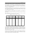
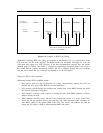
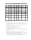
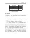
Table 1-2, Data-Module Capabilities, summarizes the capabilities of the data modules that can be
used on Generic 2 for communications over an ISDN-PRI link. For further details on each data
module, refer to About This Document for a list of related data module documents. For complete
definitions of the four DMI modes (0 through 3), refer to Digital Multiplexed Interface (DMI)
Technical Specification, Issue 3.2, November 1989 (555-025-204). Ask for the most recent version.