


8-4
MAINTENANCE AND ALARMS
●
●
Tests 4 and 5 will light the red LED on the circuit pack when facility errors cause procedure
620 to fail. Depending on the type of errors, other LEDs may be in their alarm state.
However, the circuit pack should not necessarily be replaced, because pulling the circuit
pack may cause other facility errors to be introduced.
Excessive circuit pack removals and insertions reduce the life of the carrier.
Contrary to the maintenance procedures used for the DS1/DMI, procedure 625 is not the
main tool for analyzing ISDN-PRI errors. However, procedure 625 is still useful for
analyzing problems relating to synchronization. The primary tool for isolating level-1 errors
is via procedure 620. Procedure 648 is the primary tool for analyzing level-2 faults (tests 1
and 2) and level-3 faults (test 3).
●
Unit type 76 shows a problem with a one or more of the D-channels on a particular ISDN-
facility. (For system 85 R2V4, unit type 76 shows the first B-channel associated with a D-
channel.) Procedure 648 (ISDN facility testing) is used to provide end-to-end verification
of the transmission path and to display failure history of the ISDN level-2 faults. It consists
of three separate tests.
NOTE: Procedure 648, test 3, requires that the D-channel be up and functioning.
●
●
Test 1 is the default test for R2V4 and Generic 2. It is used to examine error
information (failure history) logged against ISDN-PRI facilities. The failing facility is
identified by physical equipment location. Its alarm status is also displayed. A failing
circuit index is provided to present the total number of failing circuits when the first
failing circuit is displayed. Test one is also used to resolve any (individual) or all
ISDN-PRI alarmed circuit failures.
Test 2 is an active “once-through” test and provides an ISDN level-2 test. Its primary
function is to send a test frame to the far end via the D-channel for that interface
associated with the selected trunk and to then verify the response. A particular circuit
or a range of circuits can be checked. The status of each failed circuit and the
associated trunk group, trunk number, and physical equipment location can be
displayed.
●
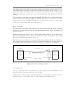
Test 3 does a level-3 loopback. A test call is made from a Generic 2 analog/digital-
facility test circuit (ADFTC) or maintenance test controller panel (MTCP) to a
terminating test line (TTL) on the far end. The test call originates on the B-channel to
be tested. When the connection is made, a framed digital pattern is sent from the
ADFTC/MTCP (originating end) to the far end where it is looped back to the
ADFTC/MTCP for bit- and block-error rate analysis. The status (fault code as well as
bit- and block-error rate calculations) of each failed circuit and the associated trunk
group, trunk number, and physical equipment location can be displayed after testing.
Depending on whether procedure 260 is translated for ZCS or B8ZS, procedure 648 will test
the channels (as appropriate) for unrestricted or restricted data.
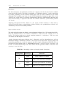
Procedure 648 test 2 (for R2V4) and test 3 (for R2V4 and Generic 2) displays the current
status of any or all B-channels in field 9. These states are:
0
1
2
Idle
In use
In use for far-end test call