


■
■
■
■
■
■
■
■
■
■
■
■
■
■
■
■
■
■
■
■
■
■
■
■
■
■
■
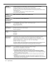
Electrical
10 Watts (35 BTU/hour) per 400 module, normal and maximum power consumption
Specifications
65 Watts (225 BTU/hour) per 206 module during normal operation
100 Watts (350 BTU/hour) per 206 module during maximum power consumption
8 Amps maximum current at full system capacity (two carriers with processor module and four
206 modules each)
On a PARTNER
II
220V System: 4.4 Amps maximum current
4-day memory backup (96 hours)
Primary
68000 microprocessor, 256Kbytes RAM, 512Kbytes ROM
Processor Module
Specifications
Expansion
8051 microprocessor, 12mHz, 8Kbytes ROM
Processor Module
Specifications
Extension Jack
Ringing voltage: +5VDC, -140 VDC peak to peak; trapezoidal wave shaping
Specifications
On a PARTNER
II
220V System: +5VDC, -150 VDC peak to peak
35- to 38-Volt talk battery
Ringing frequency: 20 Hz
PAGE Jack
Draws current on inner wire pair
Specifications
Provides contact closure on outer wire pair
600 Ohm impedance
SMDR Output
1200 baud
Format
No parity
8 data bits
2 stop bits
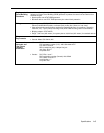
Environmental
Mount on a wall at least 2 feet (0.6 meters) from the floor (wall mounting required)
Requirements—
Locate within 5 feet (1.5 meters) of the network interface jacks and a properly grounded
Control Unit
electrical outlet not controlled by a switch, using supplied 7-foot (2.1-meter) cords
Mount the Expansion Carrier at least 6" and not more than 24" away from the Primary Carrier
Operating temperature 32° to + 104°F (0° to +40°C), not in direct sunlight
Humidity 15%–90%, noncondensing
For proper ventilation and easy replacement of modules, provide at least 6" (15.2cm) clearance
at the top and sides and 2 feet (0.6 meters) at the front and bottom of the control unit.
Locate in an area free of excess moisture, corrosive gases, dust, and chemicals
Electrical
90–130 VAC, 50–60 Hz, 3-prong outlet separate ground, separately fused at 15 Amps
Requirements
On a PARTNER
II
220V System: 180–264 VAC, fused at 10 Amps
Outlet must not be controlled by an on/off switch
Grounding to comply with Underwriters Laboratories (UL) 1459:
A. An insulated grounding conductor that is not smaller in size and equivalent in insulation
material and thickness to the grounded and ungrounded branch circuit supply conductors,
except that it is green with or without one or more yellow stripes, is to be installed as part of the
circuit that supplies the product or system.
B. The grounding conductor mentioned in item A is to be connected to ground at the service
equipment.
C. The attachment-plug receptacles in the vicinity of the product or system are all to be of a
grounding type, and the grounding conductors serving these receptacles are to be connected
to earth ground at the service equipment.
A-2
Specifications