


95
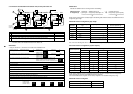
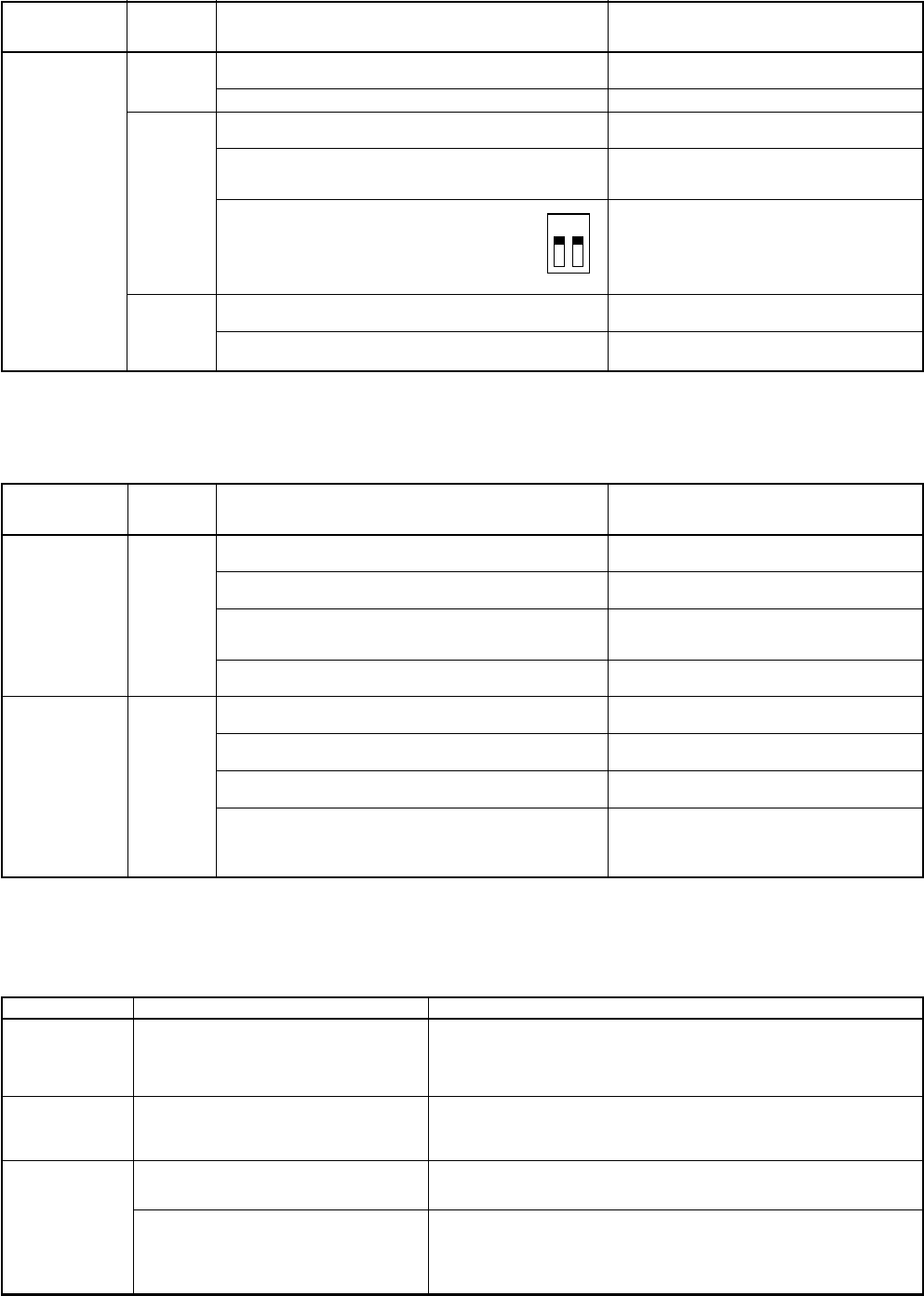
ON
1
SW30
2
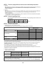
8-5-2. Operation from remote controller is not accepted and a check code is dis-
played on 7-segment display of the interface P.C. board of the outdoor unit.
8-5-3. There is no display of a check code on 7-segment display on the interface
P.C. board of the outdoor unit though there is indoor unit which does not
accept the operation from the remote controller.
8-5-4. In check for No. of connected outdoor units and connected Indoor units
after address setup, diminished No. of connected units displayed.
(There are outdoor/indoor units which do not operate in a test operation.)
Remote
controller status
No response
7-segment
display of
outdoor unit
L08
E19-00
E20-01
Cause
Line addresses and indoor addresses of all the connected
indoor units are unset.
There is no outdoor unit of group control.
Indoor unit power is not turned on.
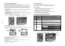
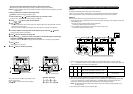
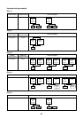
Indoor/outdoor communication line is not correctly connected
to the outdoor unit. (Fig. 1)
(Indoor/outdoor cannot communicate before address setup.)
There is none of outdoor terminator resistor,
or there are two or more resistances.
(Before address setup)
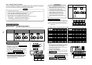
Address setup is performed with connecting indoor/outdoor
communication line between outdoor units. (Fig. 3)
Address setup is performed under condition of connecting
between multiple refrigerant lines. (Fig. 3)
Countermeasures
Set up addresses.
Set up group address.
Turn on the power again.
(In order of indoor → outdoor)
Correct wiring.
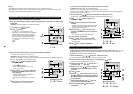
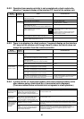
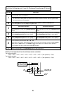
Check SW30 bit 2 of the outdoor unit.
No connection between multiple refrigerant lines:
SW30 bit 2 0N
Connection between multiple refrigerant lines:
SW30 bit 2 of the connected outdoor unit is
turned on only in one line.
Correct wiring.
Correct wiring.
Remote
controller status
No response
No display on
remote controller
(No line is output.)
7-segment
display of
outdoor unit
None
None
Cause
Communication line is not connected between indoor and
outdoor.
Line and indoor addresses are unset.
(Unit which does not response to remote controller)
The power of the header unit of the group is not turned on in
indoor group control.
(Unit which does not response to remote controller)
Group address is set up to follower unit in the individual
control. (Unit which does not response to remote controller)
The power is not turned on.
(Unit which is not displayed on remote controller)
Remote controller is not connected with cable.
(Unit which is not displayed on remote controller)
Miscabling of remote controller
(Unit which is not displayed on remote controller)
Remote controller communication circuit error
(Unit which is not displayed on remote controller)
If 230V is incorrectly applied to the remote controller terminal,
the remote controller communication circuit fails.
Countermeasures
Modify wiring.
Set up address.
Turn on the power.
Set [0] to group address in case of individual
control.
Turn on the power.
Correct wiring.
Correct wiring.
Remove FASTON terminal connected to remote
controller terminals (A/B), and check the voltage.
If voltage is not applied, replace P.C. board.
(15 to 18V usually)
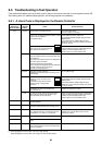
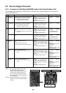
Status
Number of
connected outdoor
units is short.
Number of
connected indoor
units is short.
Number of outdoor
units connected to
group is short in
group operation
from remote
controller.
Cause
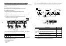
Miswiring of communication line between
outdoor units or unconnected cable (Fig. 4)
(Address setup operation has finished
without recognition of miswired follower unit.)
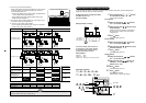
Miswiring of communication line between
indoor units or unconnected cable (Fig. 5)
(Address setup operation has finished
without recognition of miswired indoor unit.)
Remote controller is not connected with wire.
Miscabling of remote controller
Remote controller communication circuit
error
If 230V is incorrectly applied to the remote
controller terminal, the remote controller
communication circuit fails.
Countermeasures
After modification of wiring, set up address again and check No. of the
connected outdoor units.
After modification of wiring, set up address again and check No. of the
connected indoor units.
Using the main remote controller connected to a group, start a test operation,
specify the unit which does not operate (Unit unconnected to group), and then
check wiring.
Using the main remote controller connected to a group, start a test operation,
specify the unit which does not operate (Unit unconnected to group).
Remove Fasten receptacle connected to remote controller terminals (A/B),
and check the voltage. If voltage is not applied, replace P.C. board.
(15 to18V in normal time)