


86
8. TEST OPERATION
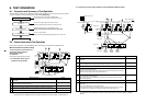
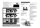
8-1. Procedure and Summary of Test Operation
A test operation is executed in the following procedure. When a trouble or an error occurs in each step, remove
causes of a trouble or an error referring to the section “9. Troubleshooting”.
Check the basic items, mainly the installation work.
Be sure to enter the check results in the check list 1 and 2.
It is the check after the power has been turned on.
Check the refrigerant circuit system is normally turned on.
Start the address setup in the outdoor/indoor units.
(NOTE) The operation does not start by only power-ON.
Carry out a test operation.
Check air blowing and cooling/heating operation in the indoor unit.
Check before test operation
Set up the addresses.
Test operation
END
Check the main power supply
is turned on.
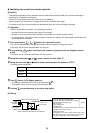
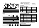
8-2. Check Items before Test Operation
Prior to the test operation, check the following items so that there is no trouble in the installation work.
Main check items for electric wiring
The communication system differs from
that of R22 or R407 refrigerant
“Modular Multi system”
air conditioner.
Check again cautious points on wiring.
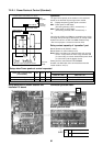
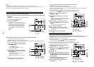
1. In case that a center control
system is not connected:
Note) The above figure does not show all the electric cables.
For details, refer to the installation manuals for outdoor unit, indoor unit, remote controller, or optional devices.
U1
U3
U2
U1
A
U2
U5 U6
U4
Header unit (A)
U1
U3
U2 U5 U6
U4
Follower unit (B)
U1
U3
U2 U5 U6
U4
Follower unit (C)
Outdoor
unit
Indoor
unit
Earth
3-phase
380-415V
Leak interception
Main switch
1-phase 230V
Leak interception
Main switch
B
U1
A
U2
B
Remote controller
U1
A
U2
B
U1
A
U2
B
1
2 4
3
5 5
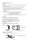
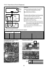
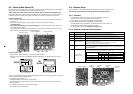
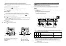
2. In case that a central control system is connected (Before address setup)
Note) The above figure does not show all the electric cables.
For details, refer to the installation manuals for outdoor unit, indoor unit, remote controller, or optional
devices.
U1
U3
U2
U4
U1
U3
U2 U5 U6
U4
U1
U3
U2
U1
A
U2
U5 U6
U4
Header unit (A)
U1
U3
U2 U5 U6
U4
Follower unit (B)
U1
U3
U2 U5 U6
U4
Follower unit (C)
Outdoor unit
Indoor unit
To indoor unit
Central control units
Other refrigerant line
Other refrigerant line
Earth
3-phase
380-415V
Leak interception
Main switch
1-phase 230V
Leak interception
Main switch
B
Remote
controller
U1
A
U2
B
Remote
controller
U1
A
U2
B
Remote
controller
U1
A
U2
B
1
2 5
3
6
6
4
No.
Main check items
Are indoor and outdoor communication lines of the header unit connected to U1/U2
terminals?
Is the relay connector between U1/U2 terminal and U3/U4 terminal removed?
(Set up at shipment from the factory)
Is the communication line between each outdoor units connected to U5/U6 terminal?
Is the terminal resistance (SW30-2) on the interface P.C. board of the header unit
turned on? (Set up at shipment from the factory)
Is the end terminal of the shield cable grounded?
Check
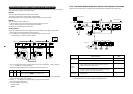
No.
Main check items
Are indoor and outdoor communication lines of the header unit connected to U1/U2
terminals?
Is the relay connector between U1/U2 terminal and U3/U4 terminal removed?
(Set up at shipment from the factory) (Before address setup, remove the relay connector.)
Is the communication line between outdoor and indoor units connected to U5/U6 terminal?
Is the communication line of the central control system connected to the header unit U3/U4
terminals of each refrigerant line?
(The communication line of the central control system may be connected to the communi-
cation lines of the indoor/outdoor communication lines.)
Is the terminal resistance (SW30-2) on the interface P.C. board of the header unit turned on?
(Set up at shipment from the factory)
(After address setup, turn off SW30-2 of the header unit except the smallest unit after
check of trial operation.)
Is the end terminal of the shield cable grounded?
When the refrigerant line and the central control system of the custom air conditioner are
connected:
→ Are TCC-LINK adaptors correctly connected?
→ When the digital inverter air conditioner operates with group operation, twin, or triple
operation, are the adopters connected to the header unit of the indoor unit?
Check