92
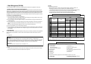
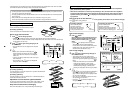
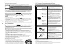
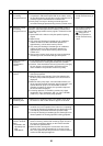
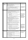
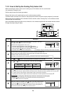
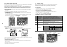
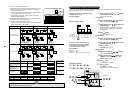
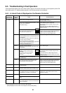
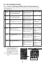
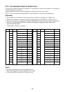
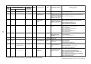
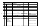
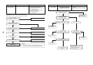
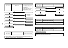
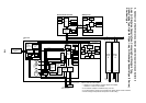
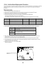
• To change all the indoor addresses from an arbitrary wired remote controller;
(When the setup operation with automatic address has finished, this change is available.)
Contents: Using an arbitrary wired remote controller, the indoor unit address can be changed for each same
refrigerant line
∗∗
∗∗
∗ Change the address in the address check/change mode.
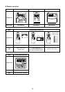
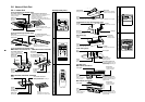
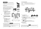
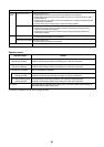
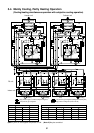
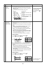
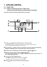
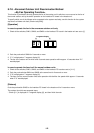
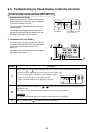
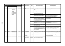
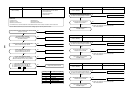
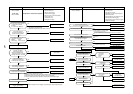
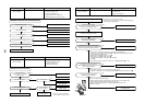
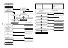
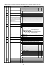
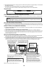
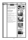
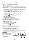
<Procedure> (Operation while air conditioner stops)
1
Push the timer time +
TEST
buttons simultaneously for 4 seconds or more.
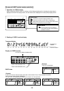
Firstly, the line 1, item code AC (Address Change) is displayed.
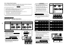
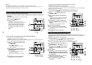
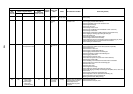
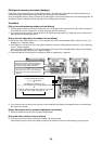
2
Using
UNIT
+
SWING/FIX
buttons, select the line address.
3
Push
SET
button.
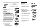
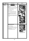
• The indoor unit address, which is connected to the refrigerant pipe of the selected outdoor unit is dis-
played and the fan is turned on.
First the current indoor address is displayed on the setup data. (Line address is not displayed.)
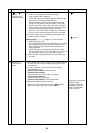
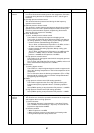
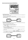
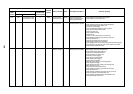
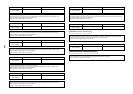
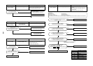
4
The indoor address of the setup data moves up/down by the timer time / buttons.
Change the setup data to a new address.
5
Push
SET
button to determine the setup data.
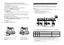
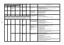
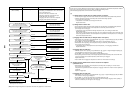
6
Every pushing
UNIT
button, the indoor unit numbers in the identical pipe are successively
displayed. Only fan of the selected indoor unit operates.
Repeat the procedure
4
to
6
and change all the indoor addresses so that they are not duplicated.
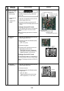
7
Push
SET
button.
(All the displays on LCD go on.)
8
Push
TEST
button to finish the procedure.
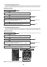
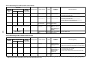
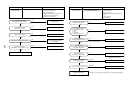
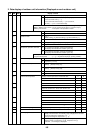
Here, if the unit No is not called up, the outdoor unit in
this line does not exist.
Push
CL
button, and then select a line according to
procedure
2
.
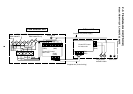
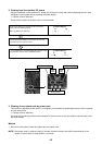
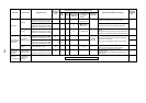
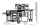
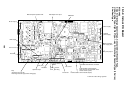
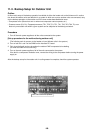
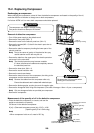
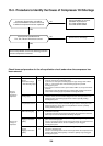
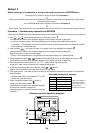
Operation procedure
1 2 3 4
5
6 7 8
End
4
8
3
1
5, 7
To finish the set
2
6
ON / OFF
FAN
TEMP.
SWING/FIXTIME
MODE
VENT
UNITSET CL
FILTER
RESET
TEST
TIMER SET
CODE No.
UNIT No.
SETTING
DATA
SET
R.C. No.
ON / OFF
FAN
TEMP.
SWING/FIXTIME
MODE
VENT
UNITSET CL
FILTER
RESET
TEST
TIMER SET
CODE No.
UNIT No.
SETTING
DATA
SET
R.C. No.
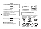
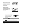
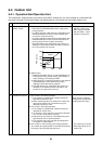
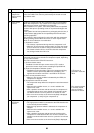
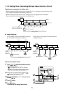
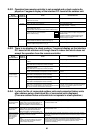
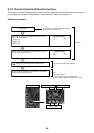
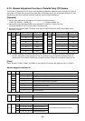
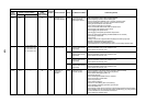
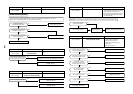
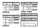
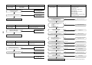
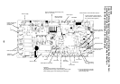
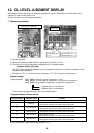
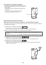
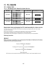
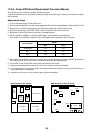
Cancel of line selection
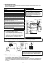
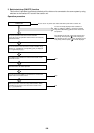
Clearance of address (Return to status (Address undecided) at shipment from factory)
Method 1
An address is individually cleared from a wired remote controller.
“0099” is set up to line address, indoor address, and group address data from the remote controller.
(For the setup procedure, refer to the abovementioned address setup from the remote controller.)
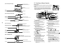
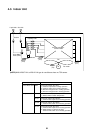
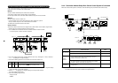
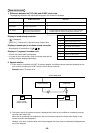
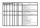
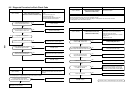
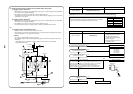
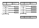
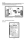
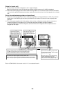
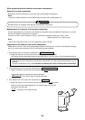
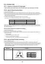
Method 2
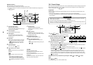
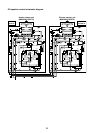
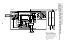
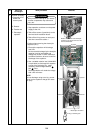
Clear the indoor addresses in the same refrigerant line from the outdoor unit.
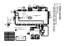
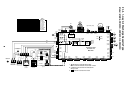
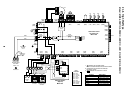
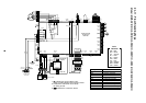
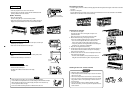
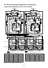
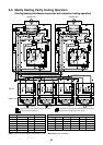
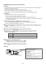
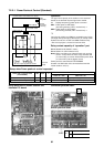
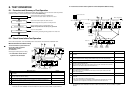
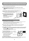
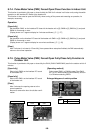
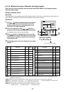
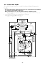
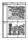
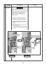
1. Turn off the power of the refrigerant line to be returned to the status at shipment, and change the header unit
to the following status.
1) Remove the relay connector between [U1U2] and [U3U4].
(If it has been already removed, leave it as it is.)
2) Turn on SW30-2 on the interface P.C. board of the header unit if it is OFF.
(If it has been already ON, leave it as it is.)
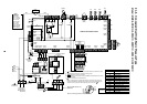
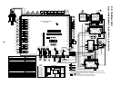
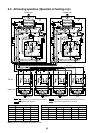
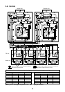
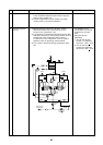
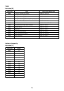
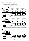
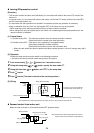
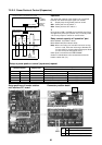
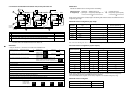
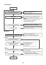
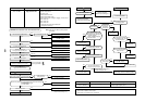
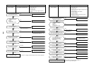
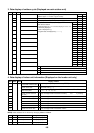
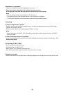
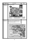
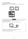
3. After “A.d. c.L.” has been displayed on 7-degment display, return SW01/SW02/SW03 to 1/1/1.
4. When the address clearing has correctly finished, “U.1.L08” is displayed on 7-degment display after a while.
If “A.d. n.G.” is displayed on 7-degment display, there is a possibility which is connected with the other
refrigerant line. Check again the relay connector between [U1U2] and [U3U4] terminals.
NOTE) Be careful that the other refrigerant line address may be also cleared if clearing operation is not
correctly executed.
5. After clearing of the address, set up an address again.
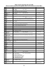
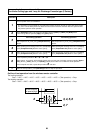
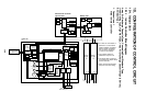
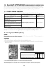
SW01 SW02 SW03
212
222
SW04
After checking that “A.d.buS” is displayed on 7-degment
display, and then push SW04 for 5 seconds or more.
After checking that “A.d.nEt” is displayed on 7-degment
display, and then push SW04 for 5 seconds or more.
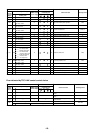
Address which can be cleared
Line + Indoor + Group address
Central address
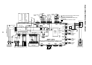
2. Turn on the indoor/outdoor power of which address is to be cleared. After approx. 1 minute, check that
“U.1. - - -” is displayed, and then execute the following operation on the interface P.C. board of the header unit
of which address is to be cleared in the refrigerant line.
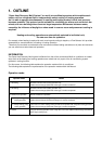
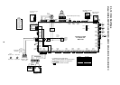
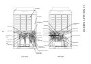
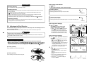
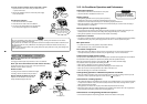
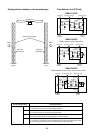
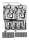
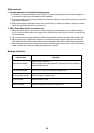
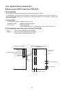
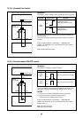
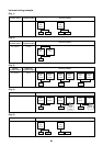
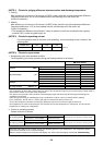
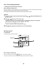
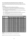
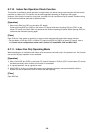
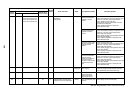
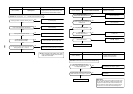
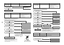
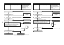
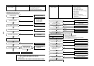
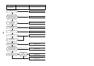
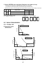
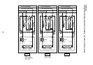
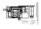
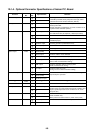
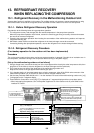
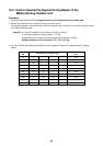
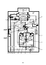
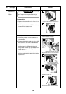
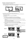
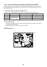
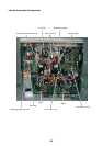
U3 U4
U1 U2 U5 U6
U1 U2
A B
Header unit
Remote
controller
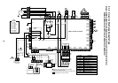
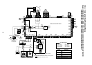
U3 U4
U1 U2 U5 U6
U1 U2
A B
Follower unit
Remote
controller
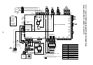
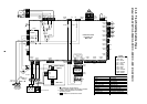
U3 U4
U1 U2 U5 U6
U1 U2
A B
Remote
controller
U3 U4
U1 U2 U5 U6
U1 U2
A B
Follower unit
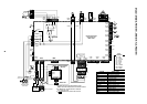
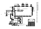
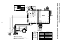
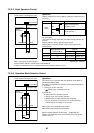
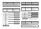
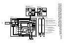
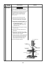
U3 U4
U1 U2
U1
U3
U2
U4
U5 U6
U1 U2
A B
Remote
controller
Center unitCenter unit Center unitCenter unitHeader unit Header unit
Central control
device
Unit of which address is to be returned to the initial status