


148
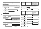
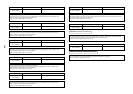
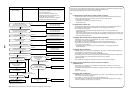
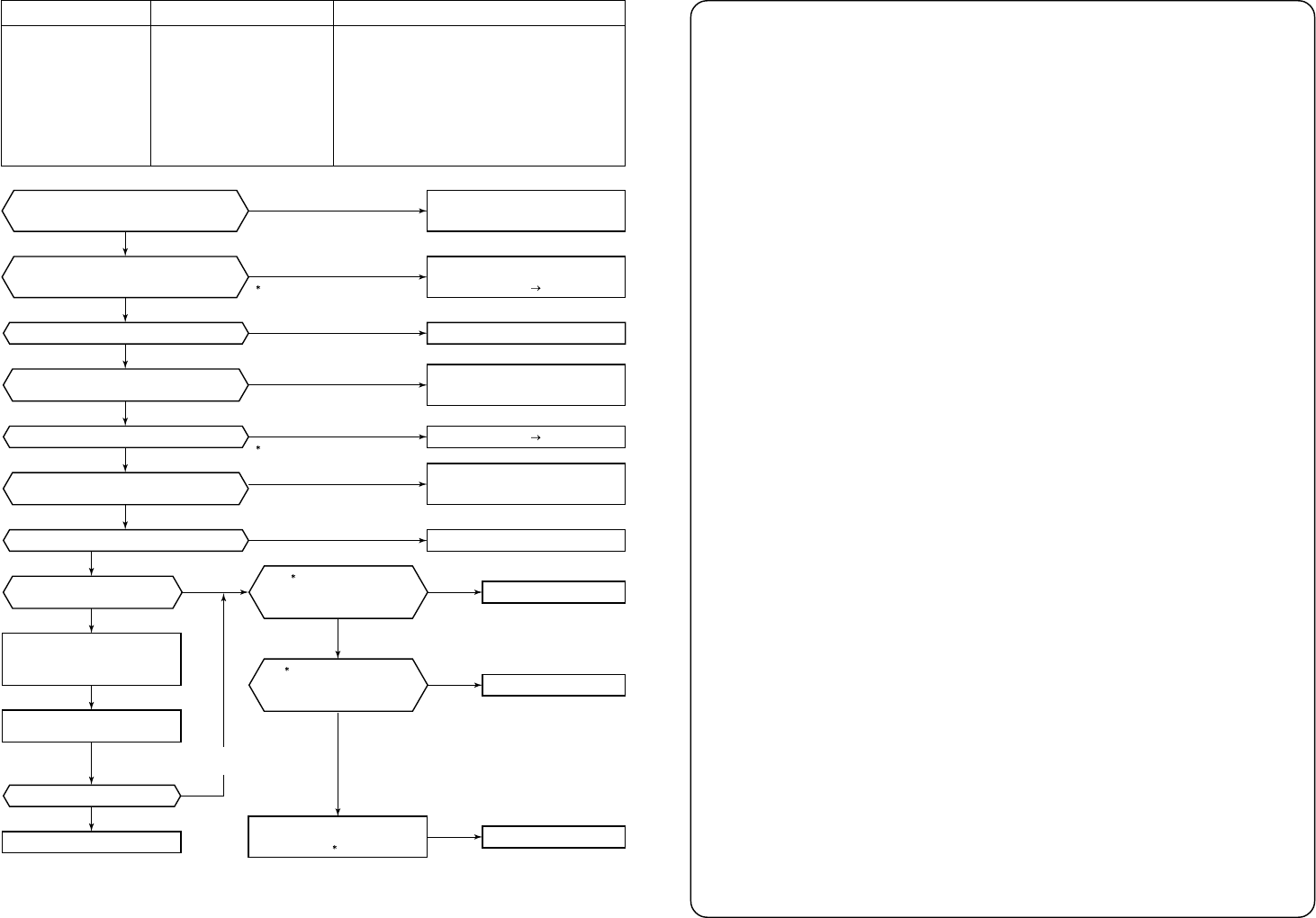
Check code
[H07] / [d7]
(TCC-L / AI-NET)
Check code name
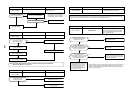
Low oil level protection
Cause of operation
1. Valves of balance pipes closed.
2. Miscabling or misinstallation of TK1 to TK4 sensors
3. TK1 to TK4 sensor error
4. Gas leak or oil leak of all outdoor units
5. Refrigerant stagnation of compressor case
6. SV3A, 3B, 3D, 3C, 3E valve error
7. Clogging of oil return circuit from oil separator
8. Clogging of oil-equation circuit system
(Note) When refrigerant stagnates in compressor shell, there may appear to be a low oil level.
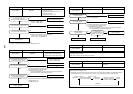
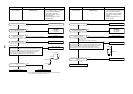
Check leakage of SV6 circuit.
Are characteristics of TK1 to TK4 normal?
Is the flow selector unit normal?
Are all the oil levels appropriate?
Eliminate cause of stagnation.
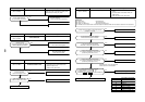
Indoor/outdoor PMV error
(Cause of refrigerant stagnation)
Discharge check valve error, etc.
Check setup of cooling only
indoor units is correct.
Check gas leak of outdoor unit.
(Check oil leak at the outdoor unit.)
Check accumulation of
refrigerant in compressor case.
Check oil level judgment
of each compressor.
YES
YES
Normal
Normal
YES
Normal
YES
Refrigerant accumulation
No leakage or clogging
No clogging
YES
Abnormal
NO
NO
Abnormal
NO
Abnormal
NO
YES
YES
Clogging
NO
NO
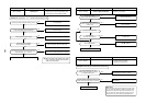
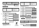
Are TK1, TK2, TK3, and
TK4 sensors connected correctly?
Is sensor fitted correctly or mis-installed.
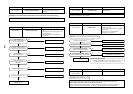
Are TK1 and TK2 sensors connected correctly?
Is sensor fitted correctly or mis-installed.
Are sensor characteristics normal?
Check clogging of
oil-equalization circuit.
( 3)
Correct miswiring.
TK1: CN514, TK2: CN515
TK3: CN516, TK4: CN523
Correct miswiring.
(TS1: CN504, TS2: CN522)
Sensor error Replace
Set up cooling only operation mode.
Item code (DN) OF
Cooling only operation mode: 0001
Determine position where
gas leaked and repair.
(Recharge, refill oil.)
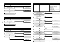
Replace defective parts.
Sensor error Replace
Repair the flow selector unit.
Replace defective parts
Replace defective parts
Replace defective parts
Correct accumulation of
refrigerant in compressor case,
reset power supply and
start operation.
( 1) Check leakage of
solenoid valve. (SV3C)
Check clogging.
(SV3E)
( 2) Check clogging in oil
recovery circuit of the oil separator.
(Capillary, Strainer)
Check clogging of SV3D valve.
( )
Characteristics-2
Characteristics-4
SW01/02/03=1/16/1 are
displayed on 7-segment display.
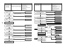
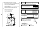
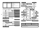
In some cases, it may be difficult to check for leakage or clogging of refrigerant in low ambient temperature condition.
In this case, it may take longer for the system to warm up before commencing checks.
(Criteria: Discharge temperature of TD1 and TD2 are 60°C or higher)
(*1)
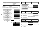
a) Leakage check for SV3A valve (for multiple outdoor unit system)
• Turn off the power supply, take off connector of SV3A valve, and then start a test operation after power-ON.
• Check the temperature change at secondary side of SV3A valve during operation
(1 in the figure on the next page).
• If temperature is increased, it is a leakage of SV3A valve.
Replace SV3A valve.
b) Leakage check for SV3C valve
• Turn off the power supply, take off connector of SV3C valve, and then start a test operation after power-ON.
• After operation for several minutes, check temperature at secondary side of SV3C valve
(2 in the figure on the next page).
• If temperature is high (equivalent to discharge temperature TD), it is a leakage of SV3C valve.
Replace SV3C valve.
(Even if there is leakage from SV3C valve does not occur, temperature of SV3C valve at secondary side
rises during operation. When the checked temperature is equivalent to TD temperature, it is a leakage of
SV3C valve. Replace SV3C valve.)
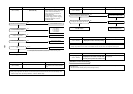
c) Clogging check for SV3B valve (for multiple outdoor unit system)
• While outdoor unit is operating, set up SW01/02/03 = [2] [1] [3] to 7-segment display [Hr], and push SW04
for 2 seconds or more, [Hr] [2] is displayed.
• Set up SW02 = [9], and turn on SV3A, SV3B, SV3C valves (7-segment display [Hr] [ 3-]).
• While outdoor unit is operating, check temperature change at secondary side of SV3B valve
(3 in the figure on the next page).
• If temperature does not rise (equivalent to suction temperature), it is a clogging of SV3B valve.
Replace SV3B valve.
d) Clogging check for SV3E valve
• While the outdoor unit is operating, set up SW01/02/03 = [2] [1] [3] the 7-segment display A displays [Hr],
and push SW04 for 2 seconds or more, [Hr] [ 2] is displayed.
• Set up SW02 = [10], and turn on SV3E valve (7-segment displays [Hr] [ ]).
• After operating for several minutes, check the pipe temperature at the secondary side of the SV3E valve.
If it is the equivalent to the outside temperature, SV3E valve may be clogged.
Replace SV3E valve.
• Note: If SV3E valve is clogged, the temperature of all TK1 to TK4 sensors do not change.
(*2) Clogging check for SV3D valve of oil return circuit from oil separator
a) Oil return circuit
• While outdoor unit is operating, check temperature (secondary side of capillary) on oil return circuit
(5 in the figure on the next page).
If temperature is equivalent to suction temperature, a clogging of strainer of oil return circuit or capillary is
considered.
Repair the clogged part.
b) Clogging check for SV3D valve
• While outdoor unit is operating, set up SW01/02/03 = [2] [1] [3] to 7-segment display [Hr], and push SW04
for 2 seconds or more, [Hr] [2] is displayed.
• Set up SW02 = [7], and turn on SV3D valve (7-segment display [Hr] [ 3d]).
• If temperature is low at secondary side of the valve or it does not change, clogging of valve, capillary, or
strainer is considered ( 6 in the figure on the next page).