115
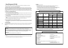
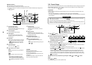
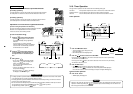
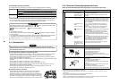
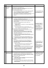
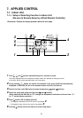
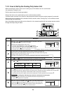
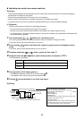
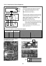
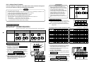
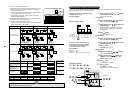
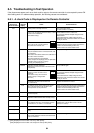
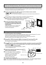
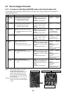
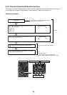
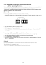
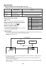
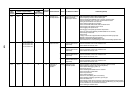
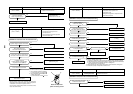
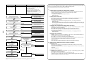
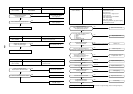
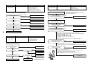
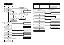
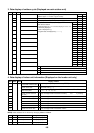
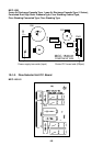
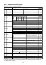
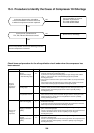
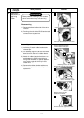
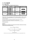
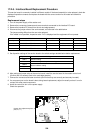
8-7-12. Monitor Function of Remote Controller Switch
When using a remote controller with the model name RBC-ATM21E, the following monitor
functions can be used.
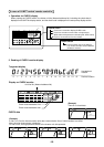
Calling of display screen
[Contents]
The temperature or the operation status of the remote controller, indoor unit, or each sensor of the outdoor unit
can be known by calling up the service monitor mode from the remote controller.
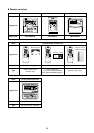
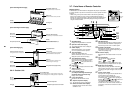
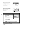
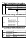
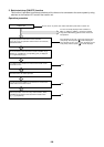
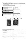
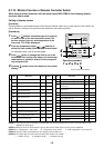
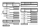
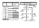
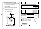
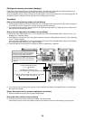
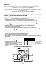
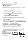
[Procedure]
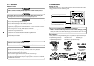
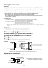
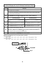
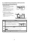
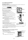
Operation procedure
1 2 3 4
1
3
4
2
Returns to the normal display
ON / OFF
FAN
TEMP.
SWING/FIXTIME
MODE
VENT
UNITSET CL
FILTER
RESET
TEST
TIMER SET
CODE No.
UNIT No.
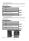
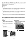
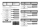
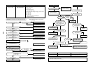
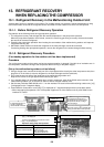
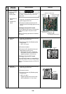
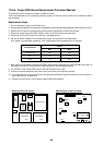
1
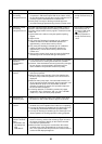
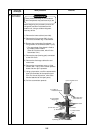
Push
CL
+
TEST
buttons simultaneously for 4 seconds
or more to call up the service monitor mode. The
service monitor goes on, and temperature of the
item code
is firstly displayed.
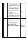
2
Push the temperature setup / buttons to
select the item number (Item code) to be monitored.
For displayed codes, refer to the table below.
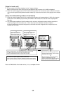
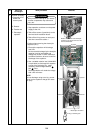
3
Push
UNIT
button to change the item to one to be
monitored. Then monitor the indoor unit and sensor
temperature or operation status in the correspond-
ing refrigerant line.
4
Pushing
TEST
button returns the display to the normal
display.
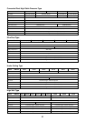
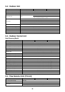
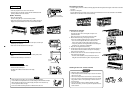
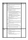
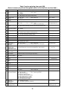
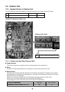
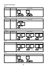
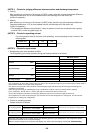
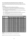
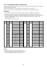
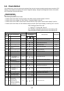
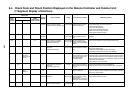
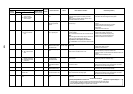
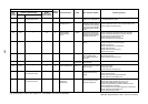
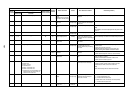
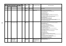
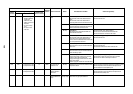
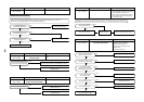
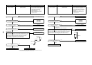
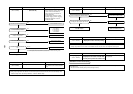
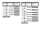
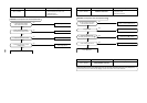
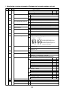
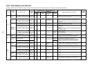
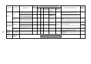
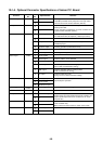
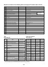
Indoor unit data (NOTE 2)
System data
Item
code
00
01
02
03
04
05
06
08
0A
0b
0C
0d
Data name
Room temp (During control)
Room temp (Remote controller)
Indoor suction temp (TA)
Indoor coil temp (TCJ)
Indoor coil temp (TC2)
Indoor coil temp (TC1)
Indoor discharge temp (Tf) (NOTE 1)
Indoor PMV opening
No. of connected indoor units
Total HP of connected indoor units
No. of connected indoor units
Total HP of outdoor units
Unit
°C
°C
°C
°C
°C
°C
°C
pulse
unit
HP
unit
HP
Display
format
× 1
× 1
× 1
× 1
× 1
× 1/10
× 10
× 10
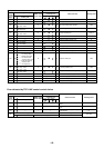
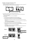
(NOTE 1) Only a part of indoor unit types is installed with the discharge temperature sensor. This temperature is not
displayed for other types.
(NOTE 2) When the units are connected to a group, data of the header indoor unit only can be displayed.
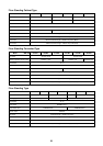
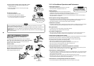
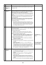
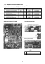
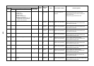
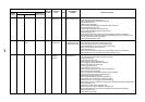
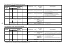
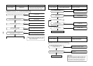
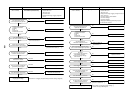
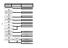
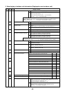
(NOTE 3) 01 : Compressor 1 only is ON. 10 : Compressor 2 only is ON. 11 : Both compressor 1 and 2 are ON.
(NOTE 4) The item codes are described as the example of the header unit.
(NOTE 5) The upper digit of an item code represents the outdoor unit number.
1 : Header unit (A) 2 : Follower unit (B) 3 : Follower unit (C)
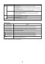
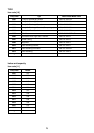
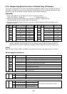
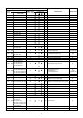
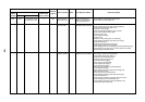
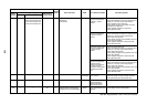
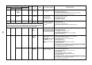
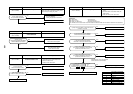
Outdoor unit individual data (NOTE 4, 5)
Item
code
10
11
12
13
14
15
16
17
18
19
1A
1b
1d
1E
1F
Data name
Compressor 1 discharge temp (Td1)
Compressor 2 discharge temp (Td2)
High-pressure sensor detention
pressure (Pd)
Low-pressure sensor detention
pressure (Ps)
Suction temp (TS)
Outdoor heat exchanger temp (TE)
Temp at liquid side (TL)
Outside ambient temp (TO)
Low-pressure saturation temp (TU)
Compressor 1 current (I1)
Compressor 2 current (I2)
PMV1 + 2 opening
Compressor 1, 2 ON/OFF
Outdoor fan mode
Outdoor unit HP
Unit
°C
°C
MPa
MPa
°C
°C
°C
°C
°C
A
A
pulse
—
—
HP
Display
format
× 1
× 1
× 100
× 100
× 1
× 1
× 1
× 1
× 1
× 10
× 10
× 1/10
(NOTE 3)
0 to 31
× 1