


224
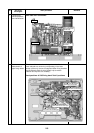
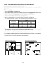
17-2-5. Interface Board Replacement Procedure
This service board is commonly installed in different models. If the board assembly is to be replaced, check the
displayed inspection contents and replace the board with the correct version for the model and follow this
procedure.
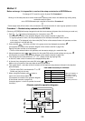
Replacement steps
1. Turn off the power supply of the outdoor unit.
2. Remove the connectors, fasteners and screw terminals connected to the interface P.C. board.
3. Remove the interface P.C. board from the six card edge spacers.
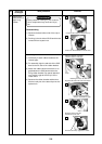
4. Disconnect the jumper wires of the service board, as instructed in the table below.
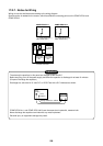
The jumper setting differs from the one to be replaced.
If the model is not specified, inspection code “L10” is displayed and the equipment will not operate.
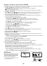
6. After setting the jumper wires of the service board, install the service board in the outdoor control unit
(Confirm that it is securely fixed to the card edge spacers.)
7. Connect the connector and fasten terminals (confirm that they are correctly and securely inserted).
8. If a component part on the board is bent during board replacement, adjust it manually so that it is not in
contact with other parts/components.
9. Install the cover then turn on the power supply.
Check the operation.
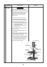
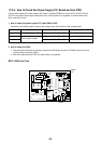
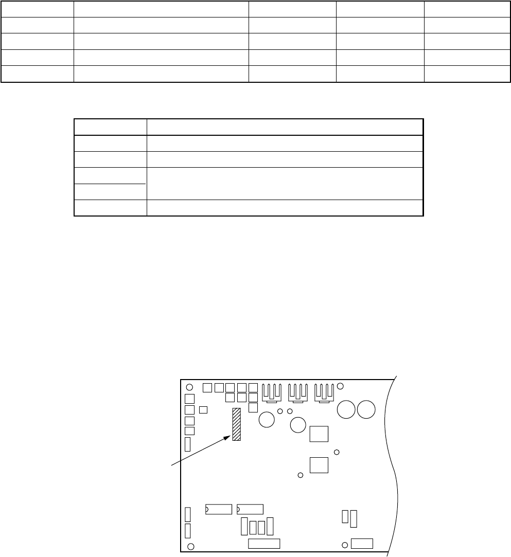
Jumper wire replacement place
(J09, 10, 11)
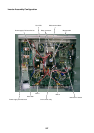
IC02
IC01
CN314
IC300 IC301
CN311
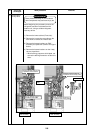
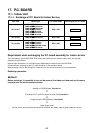
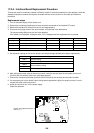
5. Set dip switch settings of the service board to the switch settings detailed below before replacement.
No.
At shipment
1
2
3
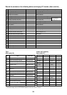
Model name
Service P.C. board
MMY-MAP0802FT8-INV
MMY-MAP1002FT8-INV
MMY-MAP1202FT8-INV
J09 J10 J11
Ye s Yes Ye s
Disconnect Disconnect Leave intact
Leave intact Disconnect Leave intact
Disconnect Leave intact Leave intact
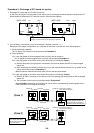
Dip Switch
SW07
SW10
SW13
SW14
SW30
Setting contents
Demand setting
Outdoor fan high static pressure setting, etc.
System address setting
Terminating resistance setting