


211
No.
5
Part to be
exchanged
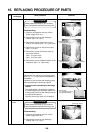
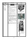
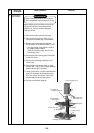
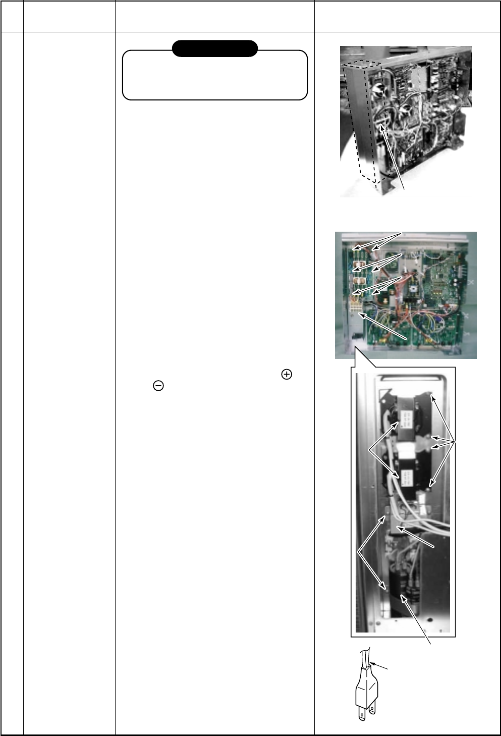
Inverter assembly
M Removal of P.C.
board and
electric parts
5. Reactor
6. Transformer
7. Electrolytic
capacitor
Work procedure
REQUIREMENT
Wear protective clothing on your hands
as other components may cause and
injury etc.
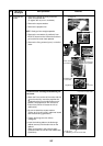
1) Stop operation, and then turn the power
supply to the unit.
2) Take off the screws (3 positions) on the
terminal block installation board.
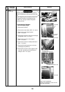
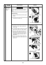
3) Take off the fixing screws on each part
and then remove the cables. ∗
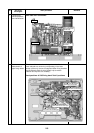
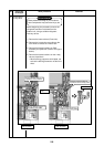
∗ Caution when removing the electrolytic
capacitor (No.7)
1) Electrolytic capacitors will discharge
over time.
As the natural discharge by the electlytic
capacitor may be unavailable and
voltage may remain in some cases due
to trouble conditions, be sure to confirm
discharge of the capacitor.
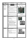
2) Use a suitable resistive load (100Ω/40W
or equivalent) to discharge the capacitor
or plug of the soldering iron, make
continuity and discharge between
and poles.
Recommendation will check the voltage
with a DC volt meter.
NOTE
Do not discharge using a tool (e.g. screw-
driver) as the capacitor charge can cause
an injury.
Remarks
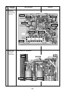
2)Screw2) Screw
7. Electrolytic condenser
2)Screw2) Screw
2)Screw2) Screw
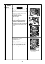
5. Reactor
(2 pieces)
5. Reactor
(2 pieces)
3)Screw3) Screw
3)Screw3) Screw
6.
Transformer6. Transformer
Plug of soldering iron
Terminal block
installation board
Terminal block
installation board
Reactor, transformer and electrolytic
condenser are stored at the rear side
of the terminal block.
Reactor, transformer and electrolytic
condenser are stored at the rear side
of the terminal block.