


90
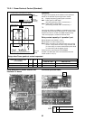
8. How to set up the terminal resistance
When all the address setups have finished in the same refriger-
ant circuit system, put the terminal resistance in the same
central control line into one.
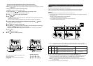
• Remain only SW30-2 of the header outdoor unit with address
1 as ON. (With end terminal resistance)
• Set up SW30-2 of the other header outdoor units to OFF.
(Without terminal resistance)
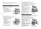
9. Connect the relay connector between [U1, U2] and [U3, U4] of
the header unit for each refrigerant line.
10. Then set up the central control address.
(For the central control address setup, refer to the Installation
manual of the central control devices.)
Note
Never connect a relay connector until address setup for all the refrigerant lines has been completed ;
otherwise address cannot be correctly set up.
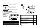
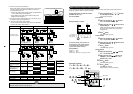
Header unit interface P.C. board
SW11
1
ON
2 3 4
SW12
1
ON
2 3 4
SW06
1
ON
2 3 4
SW07
1
ON ONON ON
2 3 4
SW09SW08
11 2 3 4
SW10
1 2 3 4
SW13
1
ON
2 3 4
SW14
1
ON
2 3 4
SW30
SW30
1
ON
2
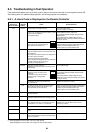
Before address setup
During setup of address
After address setup
SW13, 14
(Refrigerant line address)
SW30-2
Terminal-end resistance
of indoor/outdoor communi
cation line/central control
communication line
Relay connector
Indoor side (Automatic setup)
Refrigerant line address
Indoor unit address
Group address
1
1
0
1
2
0
2
1
1
2
2
2
3
1
0
Connect short
after
address setup
Connect short
after
address setup
Connect short
after
address setup
Setup at shipment
from factory
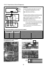
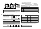
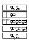
U3 U4
U1 U2 U5 U6
U1 U2
A B
Header
unit
Individual Group
Remote
controller
U3 U4
U1 U2 U5 U6
U1 U2
A B
Follower unit
Remote
controller
Relay
connector
U3 U4
U1 U2 U5 U6
U1 U2
A B
Remote
controller
U3 U4
U1 U2 U5 U6
U1 U2
A B
Follower unit
U3 U4
U1 U2 U5 U6
U1 U2
A B
Header unit
Remote
controller
Relay
connector
U3 U4
U1 U2 U5 U6
U1 U2
A B
Header
unit
Header unit
Header unit Header unit
Individual Group
Remote
controller
U3 U4
21
SW30
ON
OFF
U1 U2 U5 U6
U1 U2
A B
Follower unit
Remote
controller
Relay
connector
U3 U4
U1 U2 U5 U6
U1 U2
A B
Remote
controller
U3 U4
U1 U2 U5 U6
U1 U2
A B
Follower unit
U3 U4
U1 U2 U5 U6
U1 U2
A B
Remote
controller
Relay
connector
Relay
connector
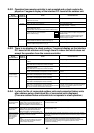
Open
ON
1 2
12 3
3 1
Header unit Follower unit Follower unitHeader unit Header unit
ON
Open Open
(Setup is
unnecessary.)
(Setup is
unnecessary.)
OFF after
address setup
OFF after
address setup
(Setup is
unnecessary.)
(Setup is
unnecessary.)
Outdoor interface
P.C. board
21
SW30
ON
OFF
21
SW30 SW30
ON
OFF
21
SW30
ON
OFF
21
ON
OFF
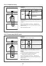
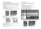
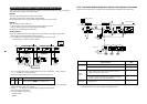
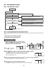
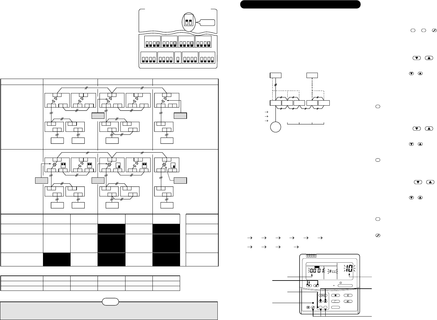
Manual address setup from remote controller
In case to decide an address of the indoor unit prior to finish of indoor wiring work and unpracticed outdoor
wiring work (Manual setup from remote controller)
Arrange one indoor unit and one remote
controller set to 1 by 1.
Turn on the power.
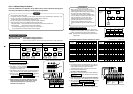
ON / OFF
FAN
TEMP.
SWING/FIXTIME
MODE
VENT
UNITSET CL
FILTER
RESET
TEST
TIMER SET
CODE No.
UNIT No.
SETTING
DATA
SET
R.C. No.
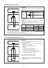
Operation procedure
1 2 3 4 5 6
7 8 9 10 11
End
11
4, 7, 10
2, 5, 8
3, 6, 9
1
Data Item code
Outdoor
Header
#1
Indoor Indoor Indoor
Line address 1
Indoor address
1
Group address
1
Outdoor
#2
Indoor Indoor
Follower
1
2
2
1
3
2
2
1
2
2
2
2
Remote
controller
(Line address)
(Indoor address)
(Group address)
(Wiring example in 2 lines)
In the above example, under condition of
no inter-unit wire of the remote controller,
set the address after individual connect-
ing of the wired remote controller.
Group address
Individual : 0000
Header unit : 0001
Follower unit : 0002
} In case of group control
1
Push simultaneously
SET
+
CL
+
TEST
buttons
for 4 seconds or more.
LCD changes to flashing.
2
Using the setup temp. / buttons,
set
to the item code.
3
Using the timer time / buttons, set up
the line address.
(Match it with the line address on the interface
P.C. board of the outdoor unit in the identical
refrigerant line.)
4
Push
SET
button.
(OK when display goes on.)
5
Using the setup temp. / buttons,
set
! to the item code.
6
Using the timer time / buttons, set up
the indoor address.
7
Push
SET
button.
(OK when display goes on.)
8
Using the setup temp. / buttons,
set
" to the item code.
9
Using the timer time / buttons, set
Individual =
, Header unit = ,
Follower unit =
.
10
Push
SET
button.
(OK when display goes on.)
11
Push
TEST
button.
Setup operation finished.
(Status returns to normal stop status.)