


87
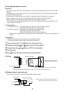
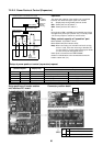
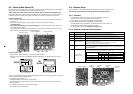
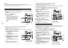
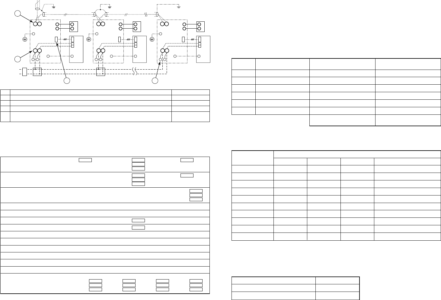
3. Connection check between Flow Selector Unit (FS Unit) and indoor unit
Note) The above figure does not cover all the electric wirings.
For details, refer to the Installation Manual of Flow selector unit.
U1/U2
LN
A
B
LN LN
A
B
Earth terminal
Earth leakage
breaker
Power switch
Pull
Box
Pull
Box
Power supply
Single phase
220-240V, 50Hz
CN02
CN81 CN81CN81
CN01
Indoor unit
Remote
controller
FS unit
Control
wiring
Power
line
Power
line
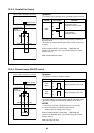
U1/U2
A
B
A
B
Earth terminal
CN02
CN01
Indoor unit
Remote
controller
FS unit
FS unit
U1/U2
A
B
A
B
Earth terminal
CN02
CN01
Indoor unit
Remote
controller
Power
line
Control
wiring
Control
wiring
Earth
terminal
Earth
terminal
Earth
terminal
Earth
terminal
Earth
terminal
Earth
terminal
1
3
2 4
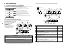
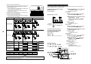
Next, refer to the following table for the corrective amount of refrigerant (B) by system capacity.
Corrective amount of refrigerant by system capacity
• Check the additional amount of refrigerant.
Check list 1
• Using the “Check list 1”, check there is no trouble in the installation work.
Is capacity of the leak Outdoor total capacity XXXX A Header unit (A) XXXX A Indoor unit XXXX A
breaker appropriate? Follower unit (B)
XXXX A
Follower unit (C)
XXXX A
Is the diameter of the power cable correctly wired? Header unit (A) XXXX mm² Indoor unit XXXX mm²
Follower unit (B)
XXXX mm²
Follower unit (C)
XXXX mm²
Is the control communication line correctly wired? Indoor –outdoor connection terminals (U1, U2) XXXX
Outdoor–outdoor connection terminals (U5, U6)
XXXX
Central control system connection terminals (U3, U4)
XXXX
Is the power of the indoor units supplied collectively?
Is the earth grounded
Is the insulation good? (10MΩ or more) XXXX MΩ or more
Is the main power voltage correct? (Within 200V ± 10%) XXXX V
Is the diameter of the connecting pipe correct?
Is the branch kit correct?
Does the indoor unit condensate drain adequately?
Is the thermal insulation of pipes good? (Connecting pipes, Branch kit)
For both indoor and outdoor units, ensure air is not short-circuited from discharge to inlet ports.
After pressure test, check that the pipework and indoor units have been vacuumed and the correct amount of additional gas has been charged.
Are valves of all the outdoor units fully opened? Suction gas side Discharge gas side Liquid side Balance side
Header unit (A)
XXXX XXXX XXXX XXXX
Follower unit (B)
XXXX XXXX XXXX XXXX
Follower unit (C)
XXXX XXXX XXXX XXXX
Check list 2
Calculate the additional amount of refrigerant from the following:
Additional amount
=
Actual liquid
×
Additional amount of
× +
Corrective amount of
of refrigerant (B) pipe length refrigerant per liquid pipe 1m
1.3
refrigerant by system capacity
(A) (B)
Firstly enter the total length for each liquid pipe in the following table and then calculate the additional amount of
refrigerant by pipe length.
Additional amount of refrigerant by pipe length
Pipe dia at
liquid side
Ø6.4
Ø9.5
Ø12.7
Ø15.9
Ø19.0
Ø22.2
Standard amount of refrigerant
kg/m
0.025 ×
0.055 ×
0.105 ×
0.160 ×
0.250 ×
0.350 ×
Total pipe length at each liquid side
=
=
=
=
=
=
Additional amount of refrigerant by pipe
length (A)
Additional amount of refrigerant pipe
dia at each liquid side kg
kg
kg
kg
kg
kg
kg
kg
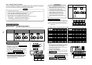
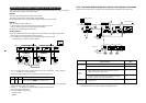
No.
Main check items
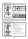
Are indoor/outdoor communication lines connected to U1/U2 terminals?
Is the signal line of the FS unit connected to connector CN81?
Is the power supply cable of the FS unit connected to R (L) and S (N) terminals?
Is the power supply cable of the FS unit connected to the closed end connector?
When the indoor unit is a Wall type (1 Series) or Concealed Duct High Static Pressure type?
Check
System horse power HP
8
10
12
16
18
20
24
26
28
30
Normal type
Unit 1 Unit 2 Unit 3 Corrective amount of refrigerant (B) kg
8 2.0
10 2.5
12 3.0
8 8 –1.5
10 8 0
10 10 2.0
8 8 8 –4.5
10 8 8 –3.0
10 10 8 –1.5
10 10 10 0
Finally add the additional amount of refrigerant by pipe length (A) to the corrective amount of refrigerant by
system capacity (B). This is the final additional amount of refrigerant.
If the result is indicated as a negative, do not add any refrigerant. Do not add the refrigerant (= 0kg).
Additional amount of refrigerant
Additional amount of refrigerant by pipe length (A)
Corrective amount of refrigerant by system HP (B)
Additional amount of refrigerant
kg
kg
kg