


36
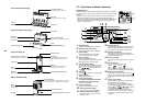
2-way discharge/3-way discharge
2-way discharge or 3-way discharge can be
selected according to the shape or
arrangement of the room.
For details, consult with the dealer
from
w
hich you have purchased the air conditioner.
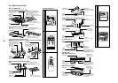
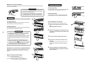
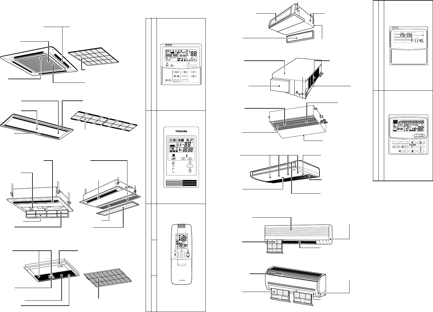
Air outlet/Air outlet louver
Select air
flow
direction in cooling or
heating operation.
Air filter
Filters dust and other trash.
(Air filter is
situated
in the air grille.)
Air inlet grille
Earth screw
Situated inside the
electric
parts box.
Clip
To
open/close the air inlet grille.
Center panel
Air inlet
Air filter
Filters dust and other trash.
(Air filter is
situated
in the
air grille
.)
Earth screw
Situated inside
the electric parts box.
Air outlet/Air outlet
louver
Select air
flow
direction in cooling or
heating operation.
Air outlet/
Air outlet
louver
Select air flow direction in
cooling or heating operation.
Earth screw
Situated inside the
electric parts box.
Air inlet grille Air inlet grille
Air filter
Filters dust and other trash.
(Air filter is situated in the air inlet grille.)
Earth screw
Situated inside
the electric parts box.
Air outlet/
Air outlet
louver
Select air
flow
direction in cooling
or heating operation.
Air filter
Filters dust and other trash.
(Air filter is
situated
in the air inlet grille.)
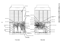
[4-way Air Discharge Cassette Type]
[2-way Air Discharge Cassette Type]
[1-way Air Discharge Cassette Type]
MMU-AP0071YH to AP0121YH MMU-AP0151SH to AP0241SH
MMU-AP0152SH, AP0182SH, AP0242SH
Button
Button to open/close
suction port
Air outlet/Air outlet
louver
Select air flow direction in cooling or
heating operation mode.
Air filter
Filters dust and other trash.
(Air filter is situated in the air grille)
Air inlet grille.
Earth screw
Situated inside the electric box.
Air filter
Filters dust and other trash.
(Provided on the suction port.)
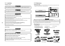
ON / OFF
FAN
TEMP.
SWING/FIXTIME
MODE
VENT
UNITSET CL
FILTER
RESET
TEST
TIMER SET
CODE No.
UNIT No.
TEST
SETTING
DATA
SET
R.C. No.
H
˚C
TEST
SETTING
WEEKLY TIMER
ERROR
SuMoTuWeTh FrSa
PROGRAM1
PROGRAM2
PROGRAM3
SELECT ZONE
CL
SET
GROUP
CODE
No.
UNIT No.
No.
R.C.
TEST
ZONE
ALL
ZONE
GROUP
SETTING
1234
SET DATA
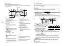
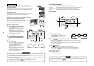
[Concealed Duct Type]
[Concealed Duct, High Static Pressure Type]
[Slim Duct Type]
[Under Ceiling Type]
[High Wall Type]
MMK-AP0071H to AP0241H
MMK-AP0072H to AP0122H
Air outlet flange
Discharge duct connection.
Earth screw
Earth screws are situated
inside the electric parts box.
Air filter
Filter dust and other trash.
(Air filter is situated in the air inlet grille.)
Air inlet
Air filter is situated in the air grille.
Air outlet
Discharge duct connection.
Air inlet
Suction duct connection.
Earth screw
Earth screws situated
in the electric parts box.
Drain pan
Air inlet grille
Earth screw
Air filter
Air outlet/Air outlet
louver
Filters dust and
other trash.
(Air filter is
situated
in
the air inlet grille.)
Situated inside
the
electric parts box.
Change the direction of the air
to be discharged according to
cool/heat mode.
Earth screw
Button
Air filter
Air filter is situated in the air grille.
(
Filters dust and other trash.
)
Air outlet/Air outlet
louver
Air inlet
grille
Situated inside the
electric parts box.
Change the direction of the air
to be discharged according to
cool/heat mode.
Air inlet grille
Earth screw
Air outlet/Air outlet
louver
Situated inside
the
electric parts box.
Change the direction of the air
to be discharged according to
cool/heat mode.
Air filter
Filters dust and
other trash.
(Air filter is
situated
in
the air inlet grille.)
Air inlet
Suction duct
connection
.
Earth screw
Situated in the
electric parts box.
Air filter
(Air filter is not
supplied on
certain models within the series.
)
Air outlet
Discharge duct
connection
.
Button to open/close the
inlet grille.
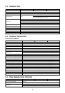
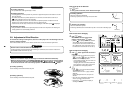
3-6. Name of Each Part
3-6-1. Indoor Unit
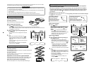
Sold Separately Parts
Main remote controller
RBC-AMT31E
Sub-remote controller
RBC-AS21E2
Wireless remote controller kit
TCB-AX21E2 RBC-AX22CE2 RBC-AX21U(W)-E2
Weekly timer
RBC-EXW21E2
Central remote controller
TCB-SC642TLE2