


53
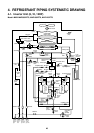
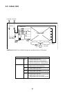
5. SYSTEM REFRIGERANT CYCLE DRAWING
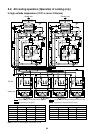
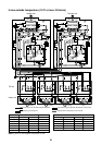
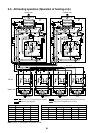
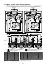
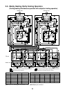
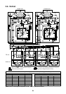
5-1. Refrigerant Piping Systematic Diagram in System
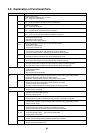
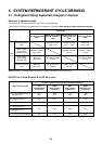
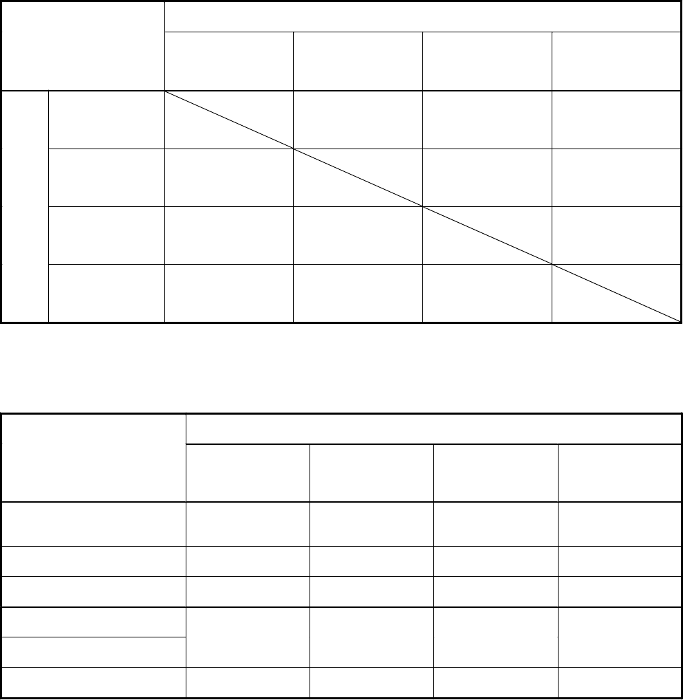
Selection of operation mode
For the selection of each operation mode, refer to the below table:
“Stop Once” this means the system does not operate for 3 minutes after operation before update has stopped.
Note) Phrases in the parentheses of the table indicate the status of the 4-way valve.
ON-OFF list of Flow Selector Unit (FS Unit) valve
After update
All coolin
g
operation
(OFF)
Mainl
y
coolin
g
, partl
y
heatin
g
cooperation
(ON)
Mainl
y
heatin
g
, partl
y
cooling operation
(ON)
All heatin
g
operation
(ON)
All coolin
g
operation
(OFF)
Operation continues
(OFF à ON)
Operation continues
(OFF à ON)
Stop Once
(OFF à ON)
Mainly cooling,
partly heating
cooperation (ON)
Operation continues
(ON à OFF)
Operation continues
(As ON)
Operation continues
(As ON)
Mainly heating,
partly cooling
operation (ON)
Stop Once
(ON à OFF)
Operation continues
(As ON)
Operation continues
(As ON)
Before
update
All heatin
g
operation
(ON)
Stop Once
(ON à OFF)
Operation continues
(As ON)
Operation continues
(As ON)
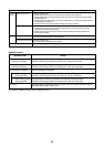
Outline of control valve output of FS unit (Basic operation)
Indoor operation mode
SVD
(High pressure
circuit valve)
SVDD
(Pressure valve
<For delay>)
SVS
(Low pressure
circuit valve)
SVSS
(Reducing valve
<For delay>)
1. Stop (Remote controller OFF)
<All system stop>
OFF
<OFF>
OFF
<OFF>
OFF
<OFF>
ON
<OFF>
2. Cooling thermo-OFF OFF OFF OFF ON
3. Cooling thermo-ON OFF OFF ON ON
4. Heating thermo-OFF
5. Heating thermo-ON
ON OFF OFF OFF
6. “E04” error is being detected OFF ON OFF OFF