


217
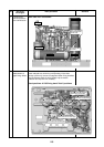
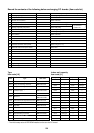
17. P.C. BOARD
17-1. Indoor Unit
17-1-1. Exchange of P.C. Board for Indoor Service
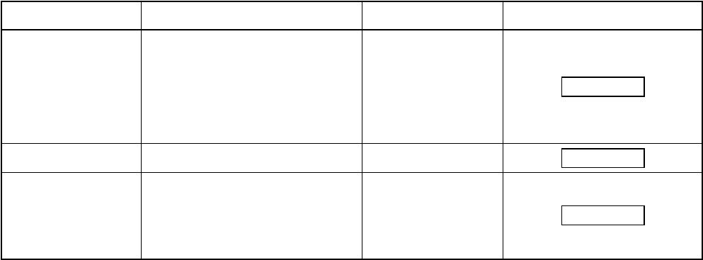
Part code
431-6V-207
431-6V-210
431-6V-269
Model type
MMU-AP
✻✻✻✻
✻✻✻✻
✻✻1WH series
MMU-AP
✻✻✻✻
✻✻✻✻
✻✻1YH series
MMU-AP
✻✻✻✻
✻✻✻✻
✻✻1SH series
MMD-AP
✻✻✻✻
✻✻✻✻
✻✻1H series
MML-AP
✻✻✻✻
✻✻✻✻
✻✻1H series
MMU-AP
✻✻✻✻
✻✻✻✻
✻✻1BH series
MMF-AP
✻✻✻✻
✻✻✻✻
✻✻1H series
MMD-AP
✻✻✻✻
✻✻✻✻
✻✻1BH series
MMU-AP
✻✻✻✻
✻✻✻✻
✻✻1H series
MMC-AP
✻✻✻✻
✻✻✻✻
✻✻1H series
MMK-AP
✻✻✻✻
✻✻✻✻
✻✻1H series
MMD-AP
✻✻✻✻
✻✻✻✻
✻✻1SPH/SH series
MMU-AP
✻✻✻✻
✻✻✻✻
✻✻2SH series
P.C. board model
MCC-1403
MCC-1402
MCC-1402
Label display on P.C. board
03RD M01
03DD M02
03DD M03
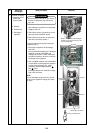
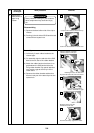
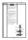
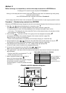
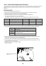
Requirement when exchanging the P.C. board assembly for indoor service
The fixed memory (herein EEPROM, IC10) stores the model type and capacity code, which are set upon
shipment from the factory.
Data set upon installation (i.e. line/indoor/group addresses) are also stored in the EEPROM.
Proceed with the exchange of the P.C. board as shown in the procedure below.
After exchange, confirm the settings for master/sub, etc. are correct and carry out a test operation.
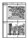
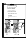
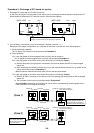
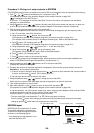
Exchange procedure
Method 1
Before exchange, it is possible to turn on the power of the indoor unit and read out the setup
contents from the wired remote controller.
Readout of EEPROM data: Procedure 1
ò
Exchange of P.C. board for service & power ON: Procedure 2
ò
Programming the EEPROM data: Procedure 3
ò
Power supply reset
(All the indoor units connected to the remote controller are reset in case of group operation control)