


51
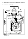
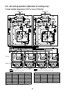
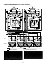
* RBM-Y1801FE has two “SVS” valves.
Check
valve
Strainer
SVS
SVSS
SVDD
SVD
Liquid pipe
Strainer
Discharge gas pipe Suction gas pipe
To indoor
gas side
To indoor
liquid side
Strainer
Capillary
tube
Capillary
tube
Capillary
tube
Check
valve
Strainer
SVS SVS
SVSS
SVDD
SVD
Liquid pipe
Strainer
Discharge gas pipe Suction gas pipe
To indoor
gas side
To indoor
liquid side
Strainer
Capillary
tube
Capillary
tube
Capillary
tube
* RBM-Y2802FE has three “SVS” valves and two “SVD”.
Check
valve
Strainer
SVS SVS
SVSS
SVDD
SVD
Liquid pipe
Strainer
Discharge gas pipe Suction gas pipe
To indoor
gas side
To indoor
liquid side
Strainer
Capillary
tube
Capillary
tube
Capillary
tube
SVS
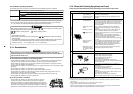
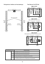
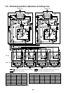
Configuration of outdoor unit heat exchanger Flow Selector Unit (FS Unit)
RBM-Y1122FE
Front side
(Right)
Rear side
(Left)
Main heat exchanger
Fan motor
Wind
Sub heat
exchanger
Wind
Sub heat
exchanger
Propeller fan
RBM-Y1802FE
RBM-Y2802FE
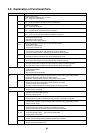
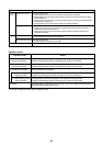
Functional part name
Solenoid valve SVD
SVS
SVDD
SVSS
Functional outline
(Discharge gas block valve)
1) High pressure gas circuit during heating operation
(Suction gas block valve)
1) Low pressure gas circuit during cooling operation
(Pressure valve)
1) For pressurizing when No. of heating indoor units increases.
(Reducing valve)
1) For recovery of refrigerant of the stopped indoor unit of which cooling thermo-OFF
2) For reducing pressure when a No. of heating indoor units decreases.