


8
5. Recharge of Refrigerant
When recharge of the refrigerant is required, charge the new refrigerant with the specified amount in the
procedure as described below.
Q
Never charge the refrigerant over the specified amount.
R
Do not charge the additional refrigerant.
If charging refrigerant additionally when refrigerant gas
leaks, the refrigerant composition in the refrigerating cycle
changes resulted in change of air conditioner characteris-
tics or refrigerant over the specified standard amount is
charged and an abnormal high pressure is applied to the
inside of the refrigerating cycle resulted in cause of
breakage or injury.
Q
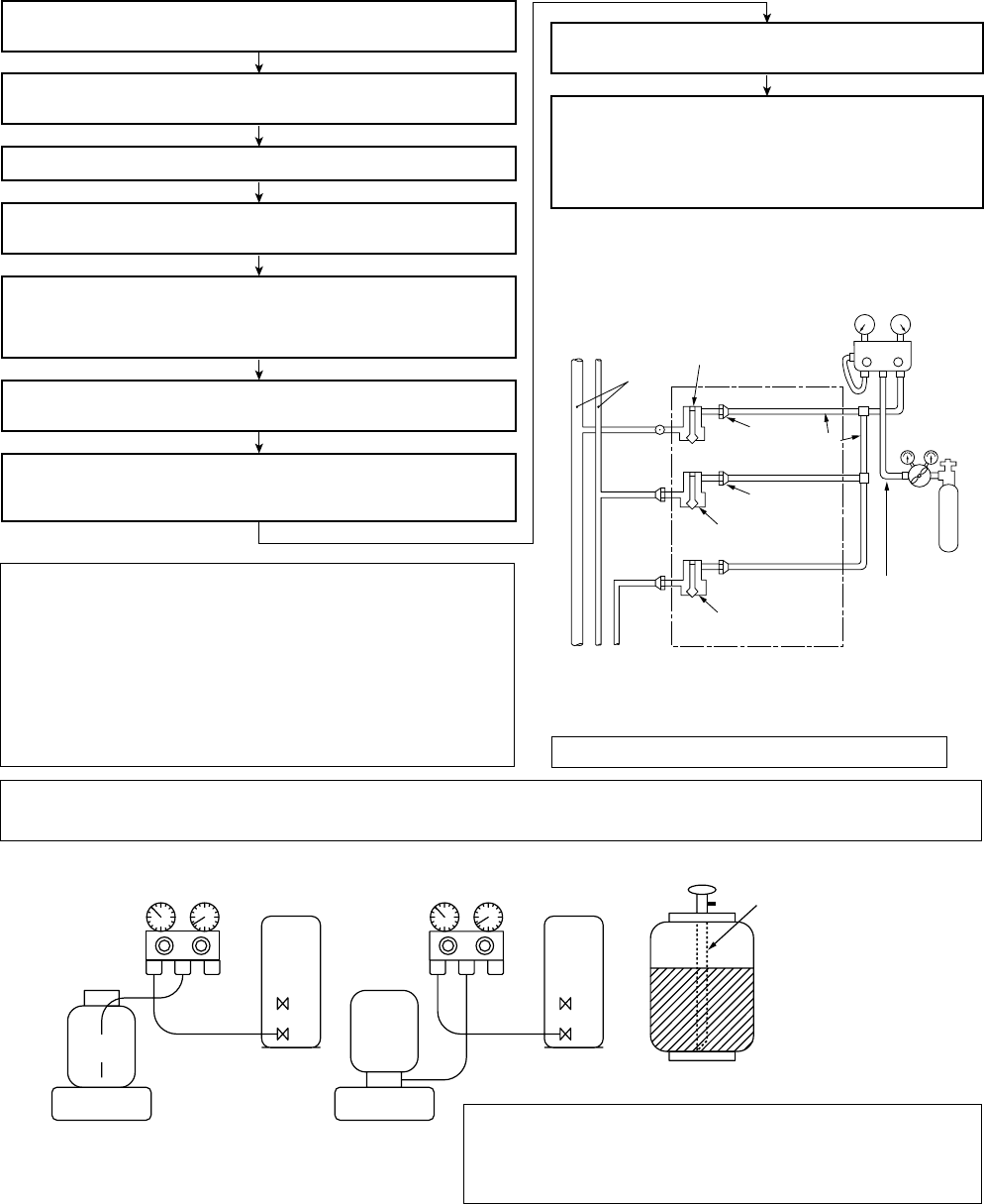
Set the equipment so that liquid refrigerant can be charged.
R
When using a cylinder with siphon pipe, liquid can be charged without inverting the cylinder.
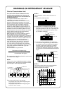
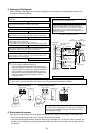
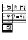
6. Environmental concern
Use “Vacuum pump method” for an air purge (Discharge of air in the connecting pipe) in installation time.
• Do not discharge flon gas into the air to protect the earth environment.
• Using the vacuum pump method, clear the remaining air (Nitrogen, etc.) in the unit. If the air remains, the
pressure in the refrigerating cycle becomes abnormally high and an injury could occur through failure of
the product.
R410A refrigerant is consisted with HFC mixed refrigerant.
Therefore if the refrigerant gas is charged, the composition
of the charged refrigerant changes and characteristics of
the equipment changes.
(Charge the refrigerant as below.)
Recover the refrigerant and check there is no refrigerant in the
equipment.
Leave it as it is for 1 to 2 minutes and check the indicator
of the compound gauge does not return.
Set the refrigerant cylinder on the electronic balance,
connect the charge hose to connecting ports of the
cylinder and the electronic gauge, and then charge the
liquid refrigerant from the service port at liquid side.
(Shield with the gauge manifold so that refrigerant does
not flow to gas side.)
Connect the charge hose to the packed valve service ports at gas
side, liquid side, and balance side of the outdoor unit.
Open the packed valves of the balance pipe fully at liquid and gas
sides, and then return the valve at gas side a little to the closed side.
Open fully PMV of the outdoor unit.
• Turn on power of the outdoor unit.
• Short CN30 on I/F P.C. board of the outdoor unit.
•
Turn off power of the outdoor unit within 2 minutes after
shorting CN30
.
Open fully the handle on the Low side of the gauge manifold, and
then turn on the power of vacuum pump for vacuuming.
When the pressure has lowered until indication of the compound
gauge pointed –0.1MPa (–76cmHg), open fully the handle Low and
turn off the power of vacuum pump.
Connect the charge hose to vacuum pump adaptor.
V
L
V
H
Connected to
indoor unit
Main
pipe
Valve fully closed
(gas side)
Center unit
Low-
pressure gauge
High-
pressure gauge
Gauge
manifold
Brazed
Service
port
Service port
Ø6.4
Copper pipe
Ø6.4
Copper pipe
Fully
tightened
Fully
tightened
Reducing
valve
Nitrogen
gas
Valve fully closed
(liquid side)
Valve fully closed
(balance)
Connected to other
terminal units
Gauge manifold
[ Cylinder with siphon ] [ Cylinder without siphon ]
OUTDOOR unit
Gauge manifold
OUTDOOR unit
Electronic
balance
Refrigerant
cylinder
Electronic
balance
Siphon
Refrigerant
cylinder
4mm-hexagonal wrench is required.