


19
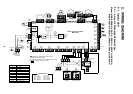
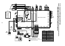
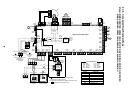
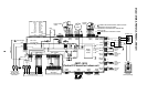
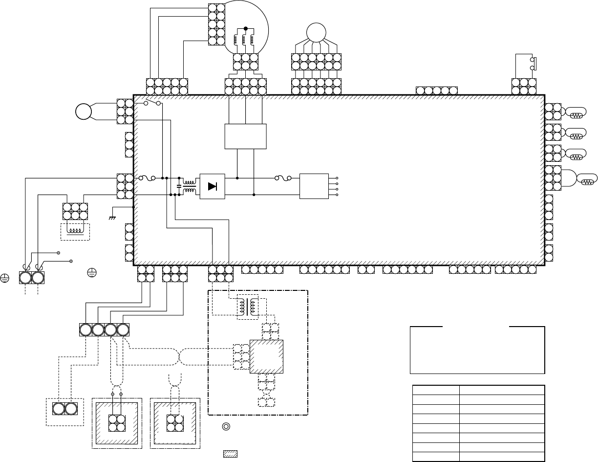
2-1-5. Concealed Duct Standard Type
Model: MMD-AP0071BH, AP0091BH, AP0121BH, AP0151BH, AP0181BH, AP0241BH
MMD-AP0271BH, AP0301BH, AP0361BH, AP0481BH, AP0561BH
CN104
(YEL)
CN102
(RED)
CN101
(BLK)
1 2 3 4 5
1 2 3 4 5 6
1 2 3 4 5 6
6 4 3 1 2 5
6 4 3 1 2 5
3 1
321
CN34
(RED)
FS
CN33
(WHI)
CN82
(BLU)
DC20V
CN68
(BLU)
CN304
(GRY)
CN66
(WHI)
CN44
(BRW)
CN67
(BLK)
Reactor
PMV
Indoor control P.C. board
1
2
1
2
TA
1
2
1
2
TCJ
1
2
1
2
TC2
CN100
(BRN)
1
2
1
2
33
CN80
(GRN)
PNL
EXCT
1
2
CN73
(RED)
1
2
(Signal output)(Fan drive)
CN70
(WHI)
CN20
(BLU)
1
2
3
TC1
1 2 3 4 5
CN81
(BLK)
CN60
(WHI)
CN32
(WHI)
CN61
(YEL)
CN50
(WHI)
Adaputor for wired
remote controller
CN309
(YEL)
CN41
(BLU)
CN40
(BLU)
T10
1 2 3 4 5
1 21 2 3 4 5 61 2 3 4 51 2 31 2 3
1 2 3
1 2 3
1 2
1 2
1 2 3
1 3
1 2 2
4 5 6
1 2
1 2
RY302
1
2
3
1
2
3
1
2
3
1
2
3
1
2
1
2
1
2
3
~
+
~
Fuse
T6.3A
250V~
Fuse
T3.15A
250V~
DC15V
DC12V
DC7V
P301
BLK
RED
WHI
WHI
WHI
RED
Wired remote
controller
1 2
BA
S(N)R(L)
U
2
1 2
CN1
(WHI)
CN001
(WHI)
Indoor unit power supply
Single phase
220-240V 50Hz
220V 60Hz
Indoor unit
Earth screw
WHI
Outdoor unit
BLK WHI BLK
BLK
BLU
BLU
BLK
BLK
TR
WHI
U
1
U
2
U
1
DM
Power
supply
circuit
Motor drive
circuit
CN01
(WHI)
CN02
(BLU)
CN03
(RED)
Network
adaptor
(Option)
1 2
1 2
1 2
1 2
X Y
3 3
2 2
1 1
Network
adaptor
P.C. board
Symbol
FM
TA
TC1,TC2,TCJ
DM
FS
RY302
PMV
Parts name
Fan motor
Indoor temp sensor
Indoor temp sensor
Drain pump motor
Float switch
Drain pump control relay
Pulse Motor Valve
Color identification
RED : RED
WHI : WHITE
YEL : YELLOW
BLU : BLUE
BRW : BROWN
BLK : BLACK
GRY : GRAY
PNK : PINK
ORN : ORANGE
GRN : GREEN
Closed end
connector
CN333
(WHI)
CN334
(WHI)
1
1
2
2
34
4
5
5
1 3 5
1 3
1 2 3
1 2 3
5
11
5
4
5
4
FM
Flow selector
unit earth
screw
1. indicates the terminal block, letter at inside
indicates the terminal number.
2. A dotted line and broken line indicate the wiring at site.
3. indicates the control P.C. board.