


77
7-1-4. Applied Control in Indoor Unit
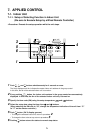
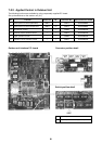
n Remote location ON/OFF control box (TCB-IFCB-4E)
[Wiring and setup]
• Use the exclusive connector for connection with the indoor control P.C. board.
• In a group control, the system can operate when connecting with any indoor unit (Control P.C. board) in the
group. However when taking out the operation/error signal from the other unit, it is necessary to take out from
each unit individually.
(1) Control items
1) Start/Stop input signal : Operation start/stop in unit
2) Operation signal : Output during normal operation
3) Error signal : Output during alarm
(Serial communication error or indoor/outdoor protective device) operation
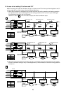
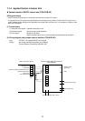
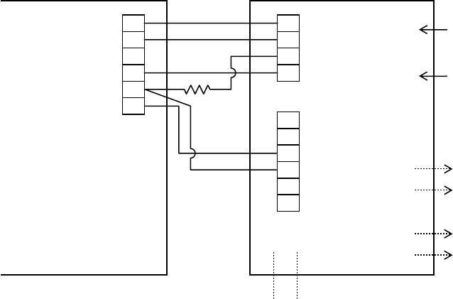
(2) Wiring diagram using remote control interface (TCB-IFCB-4E)
Input IFCB-4E : No voltage ON/OFF serial signal
Output No voltage contact for operation, error display
Contact capacity: Below Max. AC240V 0.5A
1
2
3
4
5
6
CN61
T10
(YEL)
1
2
3
4
1
2
3
4
5
6
CN13
CN06
Start/Stop input
ON/OFF serial
signal input
Indoor control P.C. board
Remote location ON/OFF control box
(TCB-IFCB-4E)
COM (GND)
Remote controller prohibition/clear input
Operation signal output
COM (+12V)
Error signal output
COM
Operation signal output
Error signal output
Power supply 220–240V,
~50Hz