


206
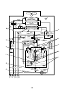
Discharge cabinet
Screws (4 corners)
5
Suction cabinet
(Front and rear)
3
Lower cabinet tab
(Front and rear)
6)Side board
(Right and left)
5)Suction cabinet
(Front and rear)
3)Lower cabinet tab
(Front and rear)
6)Side board
(Right and left)
4)Service panel
Discharge cabinet
* Hooking tab
2 × 3 positions each at
longitudinal direction
Screws (4 corners)
2)
2)
( )
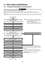
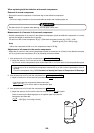
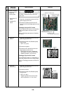
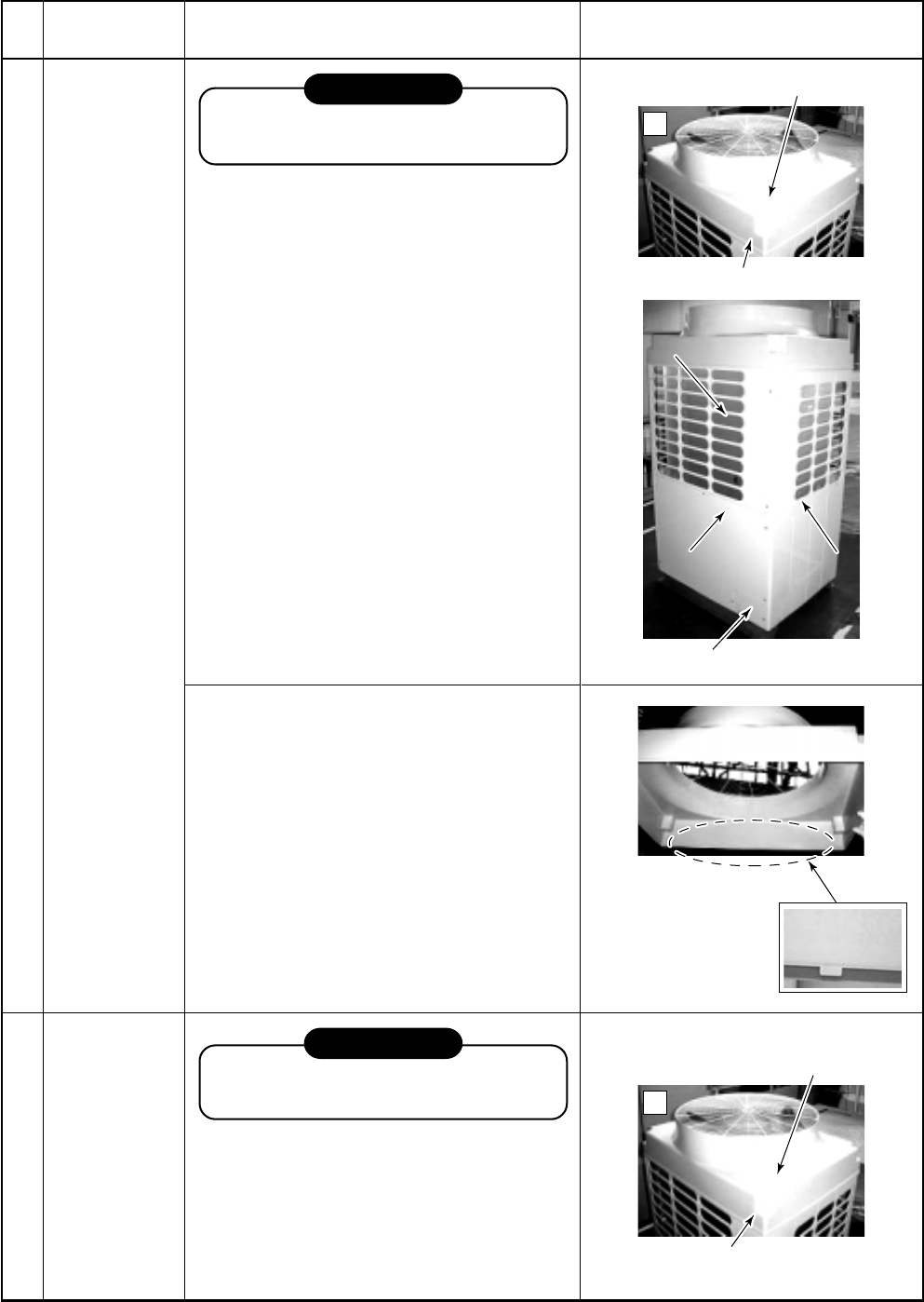
16. REPLACING PROCEDURE OF PARTS
No.
1
Part to be
exchanged
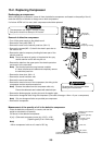
Cabinet
Work procedure
REQUIREMENT
Wear protective clothing on your hands as
other components may cause and injury etc.
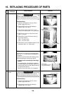
Disassembling
1) Stop the unit operation and turn off the
power supply to the unit.
2) Remove the screws on the discharge
cabinet. (M5 × 16, 4 pcs.)
3) Remove the screws (Front/rear at lower
side) on the cabinet. (M5 × 10, 7 pcs. each)
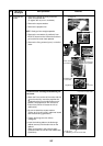
4) Remove the screws on the service panel.
(M5 × 10, 3 pcs.)
5) Remove the screws (Front/rear sides) on
the suction cabinet.
(M5 × 10, 4 pcs. each)
(M4 × 10, 2 pcs. each)
6) Remove the screws (Right/left sides) on the
side panel. (M5 × 10, 4 pcs. each)
Remarks
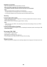
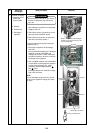
2 Propeller fan
motor
REQUIREMENT
Wear protective clothing on your hands as
other components may cause and injury etc.
Disassembling
1) Stop the unit operation and turn off the
power supply to the unit.
2) Remove the screws on the discharge
cabinet. (M5 × 16, 4 pcs.)
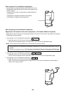
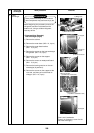
Reassembly
Reassemble the cabinet in the reverse proce-
dure ( 6) → 1) ) on the above “Disassembling
Procedure”.
However be sure to follow the following points
when assembling the discharge cabinet.
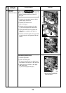
M Cautions when assembling the discharge
cabinet
The hooking tabs ∗ (6 positions) located on
the inside edge of the discharge cabinet, are
to be correctly fitted into the relevant slots on
the right/left side panels.
Failure to do so may result in unit vibration.